Notice that the signal coming from the input is divided into two paths,
known as the "Main Path" and "Ax Sidechain". The "Main Path" contains
very little processing and basically serves as a signal tap and summing point
for the Excitement circuits. In the "Ax Sidechain", the signal tap is altered
and enhanced via the rotary controls, and then is added back to the original
signal on the way to the output connector.
As a suggestion, periodically refer to the block diagram as you become
familiar with the controls and switches described below. When you have
completed this section, move on to APPLICATIONS for details on typical
settings.
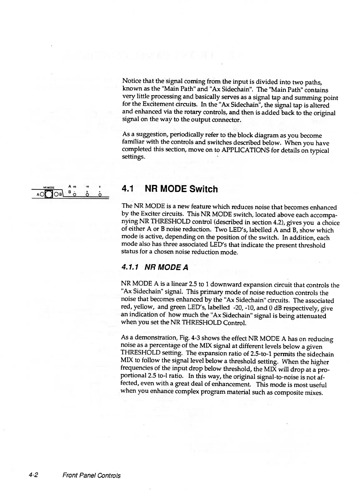
4.1 NR MODE Switch
The NR MODE is a new feature which reduces noise that becomes enhanced
by the Exciter circuits. This NR MODE switch, located above each accompa
nying NR THRESHOLD control (described in section 4.2), gives you a choice
of either A or B noise reduction. Two LED's, labelled A and B, show which
mode is active, depending on the position of the switch. In addition, each
mode also has three associated LED's that indicate the present threshold
status for a chosen noise reduction mode.
4.1.1 NR MODE A
NR MODE A is a linear 2.5 to 1 downward expansion circuit that controls the
"Ax Sidechain" signal. This primary mode of noise reduction controls the
noise that becomes enhanced by the "Ax Sidechain" circuits. The associated
red, yellow, and green LED's, labelled -20, -10, and 0 dB respectively, give
an indication of how much the "Ax Sidechain" signal is being attenuated
when you set the NR THRESHOLD Control.
As a demonstration. Fig. 4-3 shows the effect NR MODE A has on reducing
noise as a percentage of the MIX signal at different levels below a given
THRESHOLD setting. The expansion ratio of 2.5-to-l permits the sidechain
MIX to follow the signal level below a threshold setting. When the higher
frequencies of the input drop below threshold, the MIX will drop at a pro
portional 2.5 to-1 ratio. In this way, the original signal-to-noise is not af
fected, even with a great deal of enhancement. This mode is most useful
when you enhance complex program material such as composite mixes.
4-2
Front Panel Controls