6.0 CIRCUIT DESCRIPTION
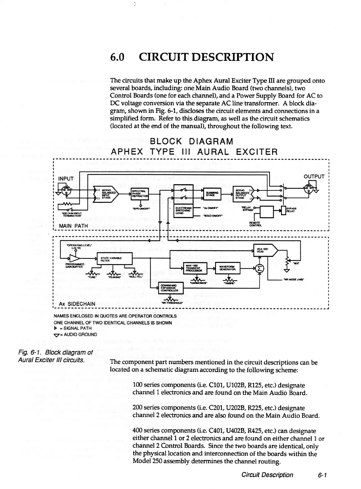
The circuits that make up the Aphex Aural Exciter Type III are grouped onto
several boards, including: one Main Audio Board (two channels), two
Control Boards (one for each channel), and a Power Supply Board for AC to
DC voltage conversion via the separate AC line transformer. A block dia
gram, shown in Fig. 6-1, discloses the circuit elements and connections in a
simplified form. Refer to this diagram, as well as the circuit schematics
(located at the end of the manual), throughout the following text.
The component part numbers mentioned in the circuit descriptions can be
located on a schematic diagram according to the following scheme:
100 series components (i.e. C101, U102B, R125, etc.) designate
channel 1 electronics and are found on the Main Audio Board.
200 series components (i.e. C201, U202B, R225, etc.) designate
channel 2 electronics and are also found on the Main Audio Board.
400 series components (i.e. C401, U402B, R425, etc.) can designate
either channel 1 or 2 electronics and are found on either channel 1 or
channel 2 Control Boards. Since the two boards are identical, only
the physical location and interconnection of the boards within the
Model 250 assembly determines the channel routing.
Circuit Description
6-1