E6 29 DTR.APC.APR.ALW.03(ENG)
Electronics casing High pressure cast of aluminium alloy, lacquered with chemical
-resistant oxide enamel, colour yellow (RAL 1003) or 1.4401 (316)
Materials for APC… APR… transmitters with diaphragm seals are described in Diaphragm Seals Data Sheets.
5.1.3. Enclosure ingress protection
IP 66,67 according to EN 60529
IP 65 according to EN 60529 with PD connector
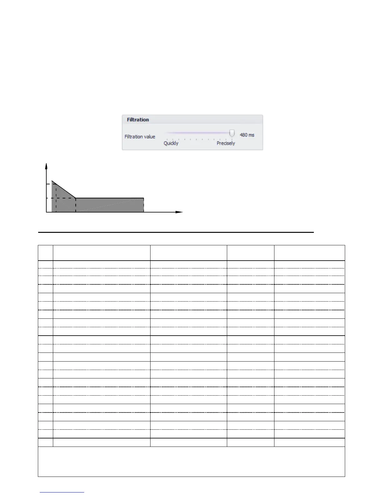
5.1.4. Response time on pressure stroke
In response to the pressure stroke measured by the transmitter - full change (100%) of the transmitter output
current is carried out over a period of one to a maximum of two values of processing time. The value of
transmitter response time can be set in the Raport 2 programme using the slider on the tab Specific parameters
-> Configuration.
5.1.5. Accuracy depending on the set range
ρ
0
– error for nominal measuring range (0...100%FSO)
ρ
1
- error for range (0...10%FSO)
ρ
1
= 2 x ρ
0
5.2. APC-2000ALW Measurement ranges and metrological parameters
5.2.1. Measurement ranges
Nominal measuring range
(FSO)
Overpressure limit
(without hysteresis) ***
0...1000bar (0...100MPa) ****
0...300bar (0...30MPa) **
0...160bar (0...16MPa) **
0...25bar (0...2.5MPa) **
-1...7bar (-100...700kPa) **
-1...1.5bar (-100...150kPa)**
-0.5...0.5bar (-50...50kPa) **
0...0.25bar (0...25kPa) **
-100...100mbar (-10...10kPa) **
-15...70mbar (-1.5...7kPa)*/**
-25...25mbar*/** (-2.5...2.5kPa)
-7...7mbar*/** (-0.7...0.7kPa)
0...1.3bar abs (0...130kPa abs)
0...7bar abs (0...7MPa abs)
0...25bar abs (0...2.5MPa abs)
0...70bar abs (0...7MPa abs)
0...300bar abs (0...30MPa abs)
*) Transmitters not available with diaphragm seal, not available in Exd version.
**) Transmitters available only in HS version, not available with SIL2.
***) Overpressure limit can be different for version according to PED norm.
****) 0...700 bar for transmitters with 1/2NPT-M pressure connector (see note p. 5.2.5.)
podstawowy
Błąd
zakresu
Szerokość
nastawianego
 Loading...