E6 51 DTR.APC.APR.ALW.03(ENG)
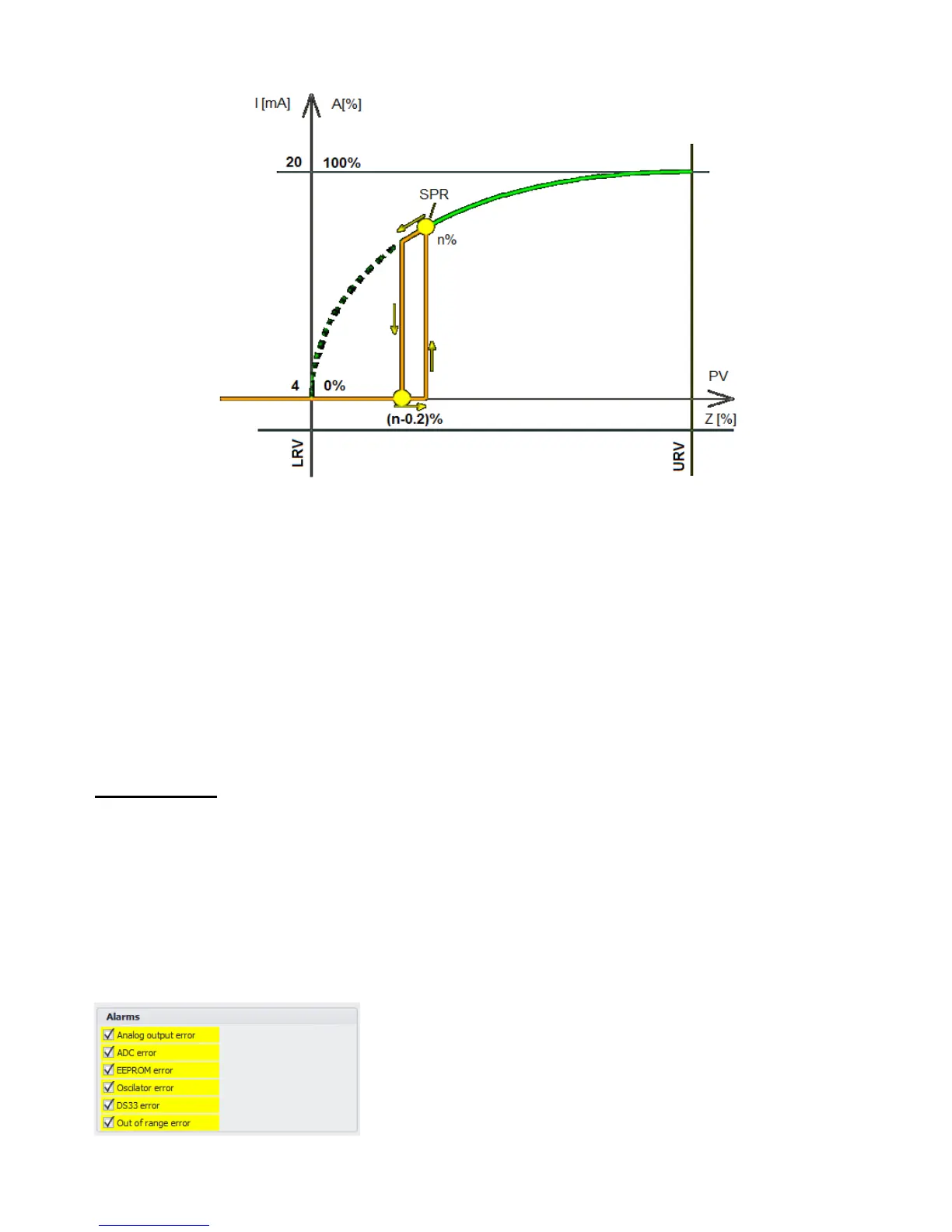
APR-2000ALW transmitter analog output signal with setting cutoff point in n%.
The device configuration example:
Transmitter configuration parameters
Basic range 0…100 kPa
Set range 0…50 kPa
Cutoff 5% of the set range
Assemble the measuring system in accordance with Figure 2 and run Raport2 according to IO.RAPORT2:
Set the zero of the transmitter – tab page: Basic Commands → Zeroing;
Set the width of the set range the transmitter to a value of 0 ... 50 kPa - tab page: Common Parameters →
Lower Range Value and Upper Range Value
Set the square root output signal of transmitter – tab page: Common Parameters → Transfer Function;
Enter 5 in the parameter area inflection point – tab page: Common Parameters → Start point rad;
Save the data to the transmitter (button: Write Parameters).
The cutoff function will be implemented to 5% of set range with pressure increase and to 4.8% of set range with
a pressure decrease
10.3. Alarms
The alarms indicate exceeding the operating parameters of the transmitter (maximum temperature, pressure),
and failures of the electronic components.
You can see the diagnostic checklist of alarm statuses by using RAPORT 2 software after reading transmitter
parameters. In this way, the values of the alarm current in the line can also be set to <3.7 (low) or >21.5 mA
(high), as well as a suitable configuration of alarms in the transmitter can be ordered from the manufacturer.
Due to extensive diagnostics mechanisms, the alarms were grouped by type in order to simplify the user
interface. The user can decide what type of alarm will trigger the alarm current in the current loop. It is
recommended for the transmitter to operate with the alarm current function turned on.
Example:
The user can also specify the type of alarm current: >21.5 mA (high alarm) or <3.7 mA (low alarm).
 Loading...