E6 54 DTR.APC.APR.ALW.03(ENG)
15. ADDITIONAL INFORMATION
The manufacturer reserves the right to make constructional and technological changes which do not lower
the quality of the transmitters.
15.1. Related documents
- IO.KAP-03.02 – Communicator User’s Manual.
- IO.RAPORT 2 – “Raport 2” software and HART/RS232 converter User’s Manual.
- DTR.HB.01 – HART/USB converter User’s Manual.
- „INTERVAL LINEARIZATION” software.
16. FIGURES
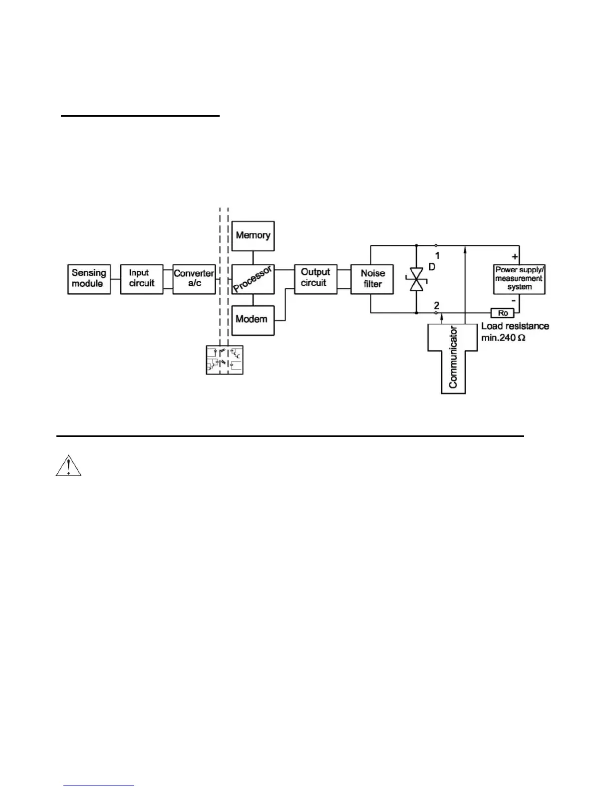
Fig. 1. APC..., APR... transmitters – block diagram.
Communicator or converter electrical connections to transmitter measuring lines.
For successful communication with transmitter the resistance in measuring loop, behind connected
device to communication, should be higher than 240Ω. If necessary install the additional resistor in
the line. The communicator or converter connecting ways to the measuring loop are presented at
diagrams. During increasing of resistance in the measure loop at making the good transmission,
is necessary to make sure that the tension falls at sum resistances in the loop don't lower minimum
tension at transmitter terminals. (see p.5.1.1)
Connection of the APC…, APR… transmitter
Connect as shown in Fig. 2a. If it is necessary to enable communication with the transmitter, a communicator or
converter can also be connected.
Optional connection configurations to communication devices are shown below.
Communicator or converter connection near to a switch box
In order to enable communication with a transmitter at a distant location via connection near to a switch box,
make sure that the resistance Ro from the point of connection of the communicator to the power supply source
lies within the range of 240÷1100 If necessary, an additional resistance can be integrated into the line.
Connect the communicator or converter as shown in Fig. 2a.
 Loading...