E6 55 DTR.APC.APR.ALW.03(ENG)
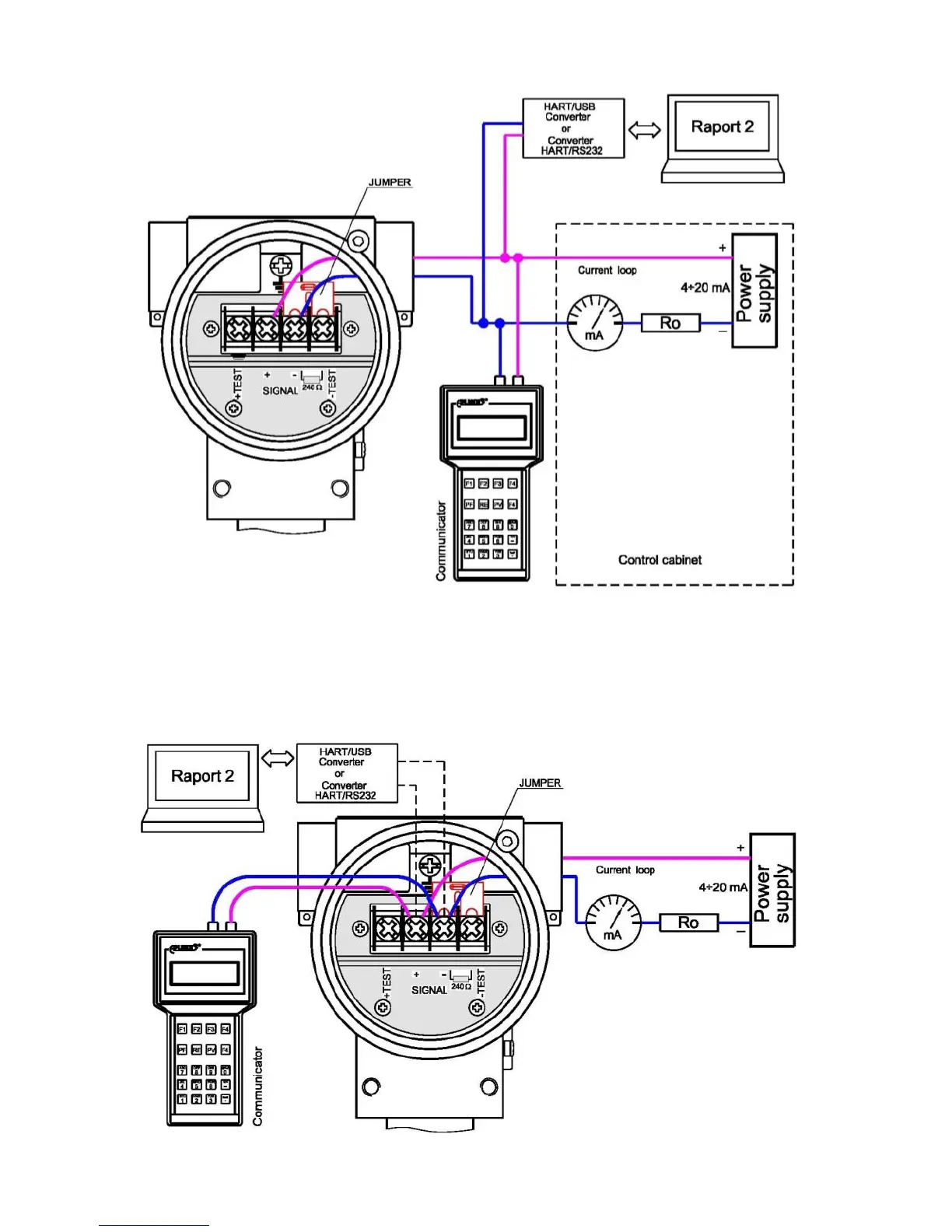
Fig. 2. Electrical connections for APC..., APR... transmitters:
Fig.2a. The link of transmitter and communicator or converter to current line by the switch box
(in case of the resistance in current loop is higher than 240Ω).
Communicator or converter connection to the transmitter’s terminals
In order to enable local communication by connecting a communicator or converter to the transmitter’s
terminals, make sure that the resistance Ro from the transmitter’s terminals to the power supply source lies
within the range of 240÷1100 If so, connect the communicator or converter to the terminals <+> <->
as shown in Fig. 2b.
Fig.2b. The link of transmitter and communicator or converter to <SIGNAL+> <SIGNAL->
transmitter terminals in case of the resistance in current loop is higher than 240Ω.
To measure the transmitter current without
disconnecting the measuring loop, connect
a milliammeter to control terminals <TEST->
and <TEST+>.
 Loading...