E6 50 DTR.APC.APR.ALW.03(ENG)
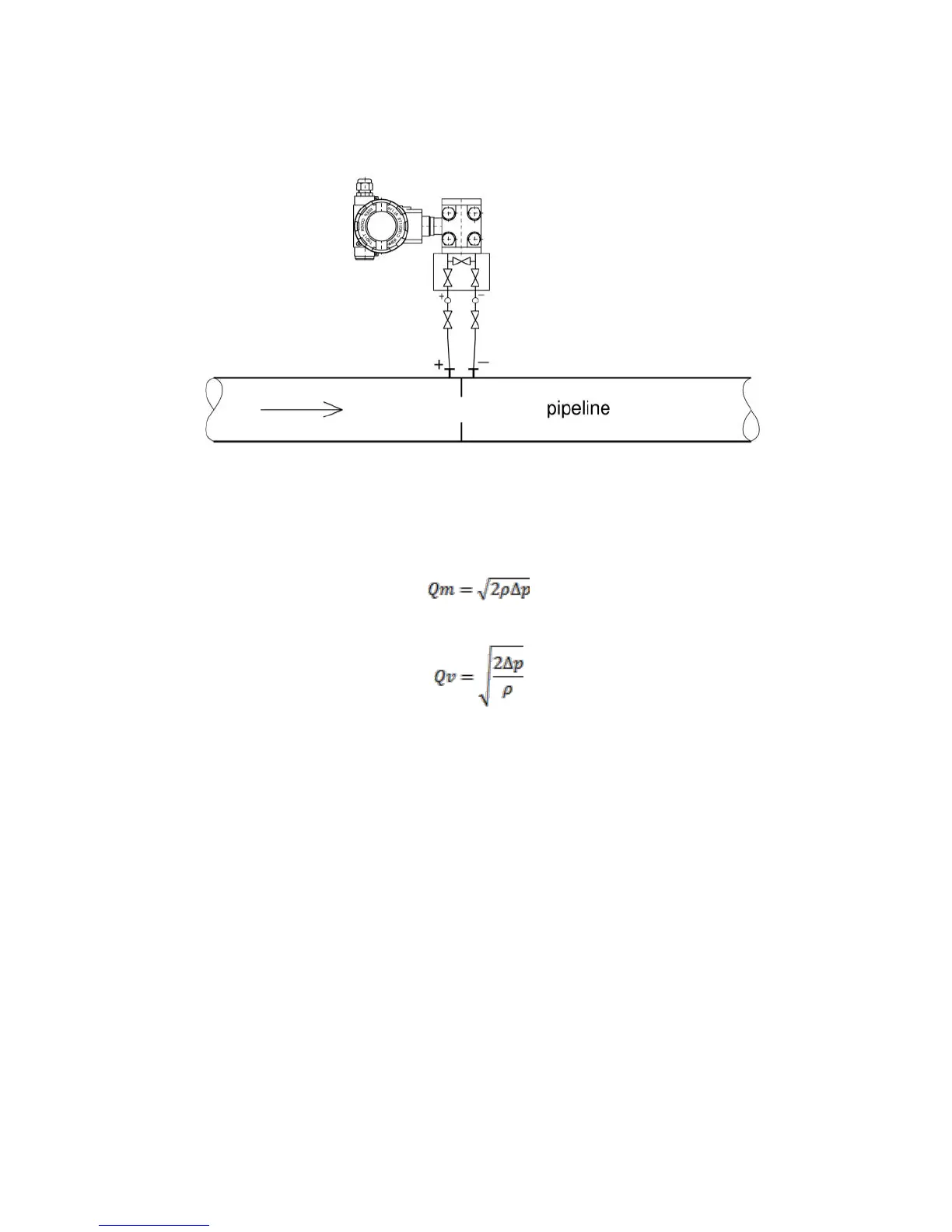
The transmitter should be located below the pipeline. It prevents the accumulation of air bubbles in the
connecting line.
Mounting diagram for gas flow:
The transmitter should be located above the pipeline. It enables the condensate flow down to the pipeline.
Function described the relationship between mass flow and differential pressure is:
Function described the relationship between volume flow and differential pressure is:
ρ – medium density
Δp – differential pressure
Orifice flow meters are based on the square root output signal from the differential pressure transmitters.
To archive this function you should:
Install the APR-2000 ALW transmitter to the flow measurement workstation with orifice;
Make the transmitter zeroing at the workstation; remotely using computer and Aplisens Raport 2 software or
locally with transmitter buttons according to p. 10.2.5 of the Manual;
Set the square root output transmitter signal and the cutoff point [in % FS]; remotely using computer and
Aplisens Raport 2 software according with p. 10.2.4 or locally with transmitter buttons (up to 1% only)
according to p. 10.2.5 of the Manual.
For transmitters with software from 1.9 version, the cutoff point setting means, that, when the pressure is increasing
from 0 to set cutoff point (n%FS), the output signal is zero (4mA), but in the setting cutoff point and above its,
the transmitter output signal passes to the square root output for the current transmitter output, and to the linear output
for the HART transmitter output. If the pressure on orifice falls below the n%FS setting minus 0.2% (hysteresis),
the output transmitter signal will switch to zero (4mA). The cutoff operation algorithm on the analog output signal
example is shown at the below figure.
Description:
I [mA] – analog output signal; loop current [4-20 mA] or A [%];
n% - cutoff point at square root output transmitter signal;
PV or Z [%] - axis of the process variable in user unit or in percent of the set range;
LRV – Lower Range Value; the lower value of the pressure set range (corresponds to the 4 mA current
output signal);
URV – Upper Range Value; the upper value of the pressure set range (corresponds to the 20 mA current
output signal).
 Loading...