E6 4 DTR.APC.APR.ALW.03(ENG)
Appendix Exd.ATEX
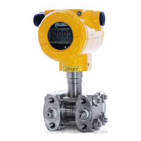
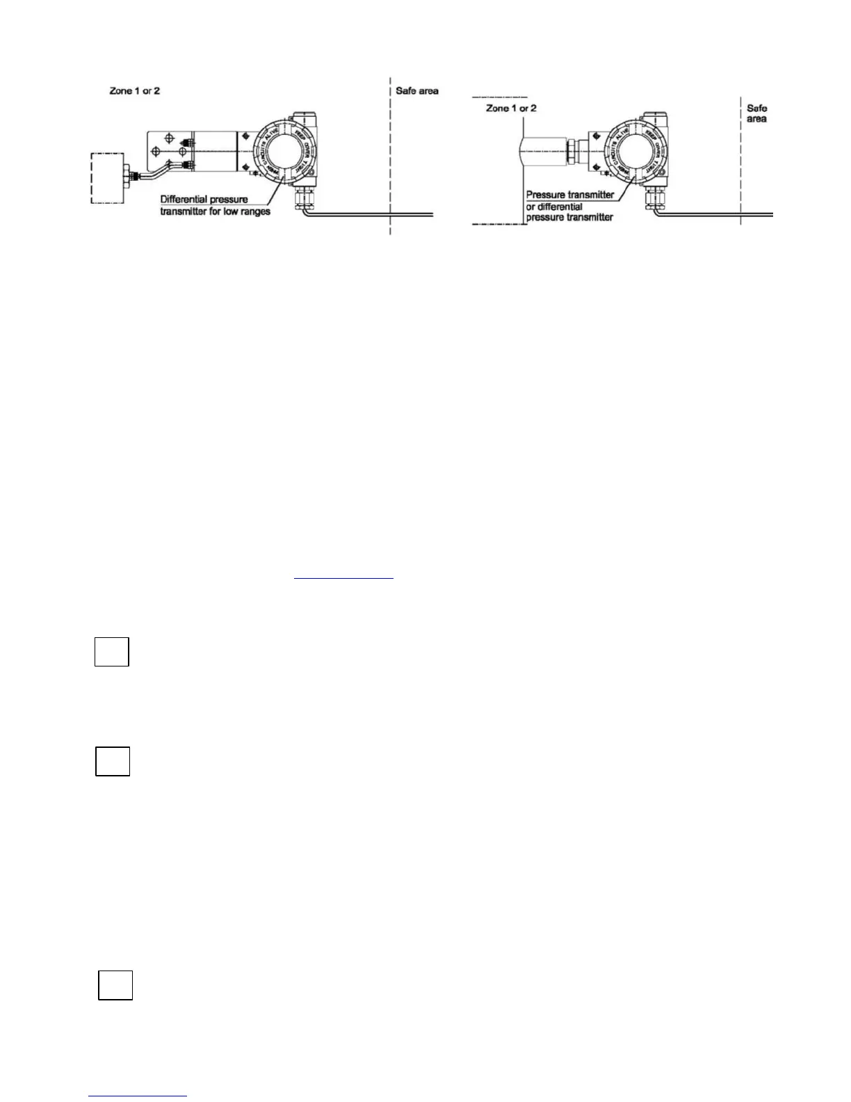
Fig.1b
3. Identifying marks
Flame-proof transmitters must have a rating plate containing the information specified in p.4 of
DTR.APC.APR.ALW.03(ENG) and also at least the following:
- CE mark and number of notified body;
- “Ex” mark, designation of explosion protection design, certificate number;
- Supply voltage;
- Designation of a process connection;
- Year of manufacture;
- Temperature use range.
In place of XX letters in product rating plate will be written a pressure connection type symbols.
4. User information
Together with the ordered transmitters, the user will receive:
a. Product Certificate;
b. Declaration of conformity;
c. Copy of certificate (on request);
d. User’s Manual named: DTR.APC.APR.ALW.03(ENG) with Appendix Exd.ATEX.
Items b), c), d) are available on www.aplisens.pl
5. Power supply and exploitation of transmitters.
5.1. The transmitter connecting should be made after introduction with present instruction content.
Electrically transmitter should be connected according to scheme at p.6 Appendix Exd.ATEX.
Transmitter electrical installation should be realised with engineering standard requirements. Electrical
connections of transmitters in danger zone should be made by people who have indispensable
knowledge and experience in this branch. Earth clamps must be used to earth transmitters. In the
event that transmitters come in contact with structural metal parts or pipes which are connected to the
equipotential bonding system, transmitters do not require to be earthed.
5.2. Transmitters should be supplied from DC electrical source with voltage max.55V from transformer
feeders or other devices which have at least a strengthened isolation among primary and secondary
windings in which don’t appear voltage higher than 250V. The duty of power supply installation with
above mentioned requirements rests on user.
5.3. Transmitters can be used in ambient temperatures (Ta) between -40ºC < Ta ≤ 45ºC for class T6 or
between -40ºC < Ta 75ºC for T5.
5.4. Transmitter sensor diaphragm should not be subject on damage during installation and
exploitation. The diaphragm is made from 1.4404/1.4435 (316L) or Hastelloy thin foil and cannot be
subject on medium which can entail its damage.
5.5. With regard on kind of casing material (light alloy with large aluminium content), the user is obliged
to assure, that possibility of hitting casing does not step out in place of transmitter installation.
5.6. In transmitter casing are two holes to assembly of cable glands from thread M20x1.5 or 1/2 NPT.
5.7. Normally transmitters are delivered without installed glands but with blank plugs (corks) in the
second hole. The list of cable glands and plugs agreeable with production documentation and accepted
by certificate station is specified in Table 1 and Table 2 (p.6 Appendix Exd.ATEX). Customer should
install cable glands according to Tables 1 and plugs according to Tables 2 (if plugs aren’t installed) or
other accordance with flame-proof standards.
 Loading...