3 CPU Core Information 17
CW6632B Bluetooth 3.0 Audio Player SOC Version 1.0.0
Copyright ©2015, www.appotech.com. All Rights Reserved.
MOVX A, @DPTR
MOVX @DPTR, A
INC DPTR
MOV DPTR, #data16
The CW6632B also offers a programmable option that automatically increases (or decreases) the contents of the
selected data pointer by 1 after the execution of a DPTR-related instruction. The actual function (increment or
decrement) is dependent on the setting of the DPAID bits. This option is enabled by setting the automatic
increment/decrement enable (DPAID: DPCON.3) to a logic 1 and is affected by one of the following 3 DPTR-related
instructions.
DPTR-related instructions are:
MOVC A, @A+DPTR
MOVX A, @DPTR
MOVX @DPTR, A
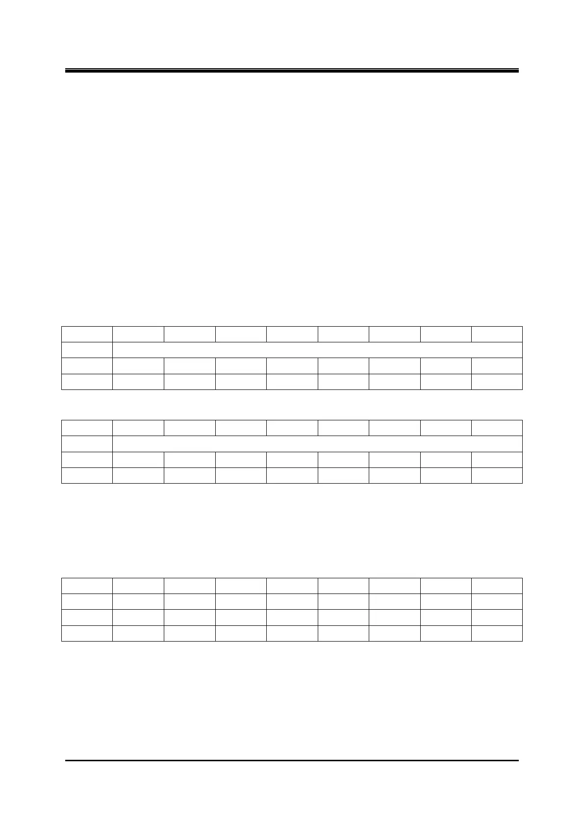
Register 3-6 SP – Stack Pointer Low Byte
Register 3-7 SPH – Stack Pointer High Byte
In a standard 8051, there is only an 8-bit stack pointer (SP). It can only use the internal 256 byte data memory as
stack memory. To increase the stack space for more complex application, CW6632B supports a 16-bit extend stack
pointer, it can use both internal data RAM and the 20K byte on-chip SRAM as stack memory. There are 2 registers
for stack control.
Register 3-8 PSW – Processor Status Word
CY: Carry Flag
AC: Auxiliary carry flag
EC: Extern instruction Carry flag
RS1, RS0: Register bank select
00 = bank0
01 = bank1