2 3
INSTALLATION
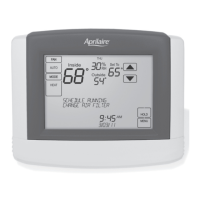
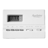
THERMOSTAT INSTALLATION LOCATION RECOMMENDATIONS
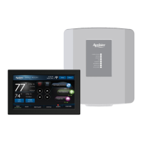
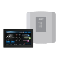
EQUIPMENT CONTROL MODULE INSTALLATION LOCATION RECOMMENDATIONS
Thermostat should be mounted:
• On an interior wall, in a frequently
occupied space.
• Approximately 5‘ above floor.
• At least 18” from outside wall.
• Thermostat can be mounted to a
vertical junction box.
Do not mount thermostat:
• Behind doors, in corners or other dead air spaces.
• In direct sunlight, near lighting fixtures, or other appliances that
give off heat.
• On an outside or unconditioned area wall.
• In the flow of a supply register, in stairwells, or near outside doors.
• On a wall with concealed pipes or ductwork.
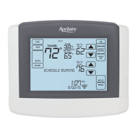
THERMOSTAT MOUNTING
1. Remove the rear mounting plate from the thermostat.
2. Pull wires through the opening on the rear mounting plate.
3. Position and level the mounting plate of the thermostat on wall and
mark the hole locations with a pencil.
4. Drill 1/4” holes and insert supplied anchors (drywall only).
5. Place mounting plate over anchors, insert and tighten screws.
6. Seal wire entry holes to prevent drafts affecting temperature readings.
Note: Installer must touch a grounded metal object before handling the equipment control module to avoid potential
damage due to electrical discharge.
Equipment control module should be mounted:
• In a location where the temperature will not exceed 158°F (70°C) or drop below 32°F (0°C).
Do not mount equipment control module:
• On foundation walls or on the HVAC equipment or ductwork. These locations can cause moisture to condense on
the equipment control module.
90-2122
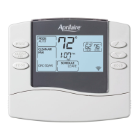
Wire specifications:
18-24 gauge thermostat wire
Installation notes:
• Ensure power at the HVAC equipment is off.
• Loosen screw terminals, insert stripped wire
and re-tighten.
• Push the excess wire back into the opening and plug the wall opening to prevent drafts.
1 – Connection to terminal 1 at equipment control module
2 – Connection to terminal 2 at equipment control module
3 – Connection to terminal 3 at equipment control module
A & B – Model 8081 or Model 8082 support module communication (optional)
T1 & T2 – Remote temperature sensor (optional)
THERMOSTAT WIRING
INSTALLATION
90-2168
EQUIPMENT CONTROL MODULE MOUNTING
The equipment control module has the following features to simplify mounting and wiring and provide for a clean
and neat installation.
• Six (6) mounting holes. One on each corner and two centered top and bottom. Any combination of these holes
may be utilized. Mount the equipment control module using 2 to 4 #8 screws appropriate for the mounting surface
substrate. (See Figure 2.)
• Wires can be routed through
the top, bottom, sides or back.
• Nylon wire ties can be used
to secure wires in 10 places.
Installation Steps
1. Select mounting location.
2. Pull from bottom to remove
front cover. (See Figure 1.)
3. Mount base using 2 to 4 #8
screws (field supplied).
Figure 1 Figure 2
 Loading...