8
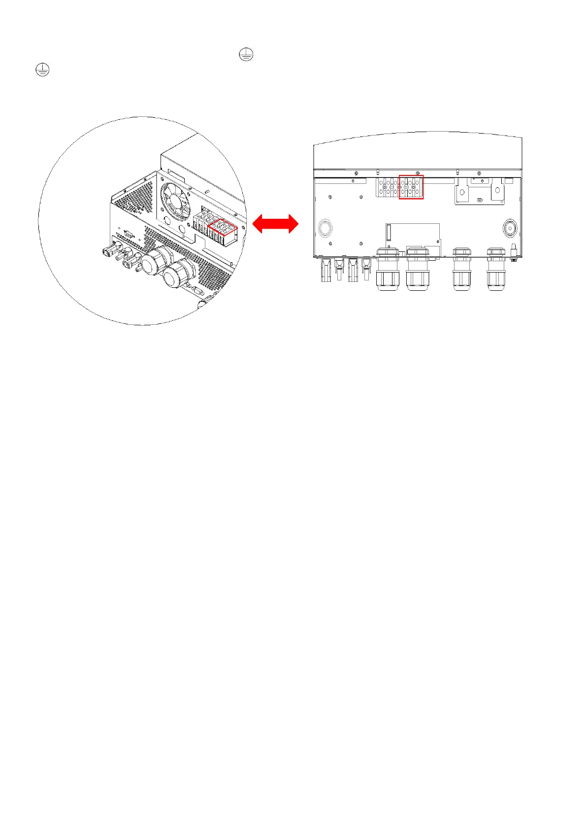
5. Then, insert AC output wires according to polarities indicated on terminal block and tighten terminal screws.
Be sure to connect PE protective conductor (
) first.
→Ground (yellow-green)
L→LINE (brown or black)
N→Neutral (blue)
6. Make sure the wires are securely connected.
CAUTION: Important
Be sure to connect AC wires with correct polarity. If L and N wires are connected reversely, it may cause
utility short-circuited when these inverters are worked in parallel operation.
CAUTION: Appliances such as air conditioner requires at least 2~3 minutes to restart because it’s required to
have enough time to balance refrigerant gas inside of circuits. If a power shortage occurs and recovers in a
short time, it will cause damage to your connected appliances. To prevent this kind of damage, please check
manufacturer of air conditioner if it’s equipped with time-delay function before installation. Otherwise, this
inverter/charger
will be trigger overload fault and cut off output to protect your appliance but sometimes
it still causes internal damage to the air conditioner.
4.6 PV Connection
CAUTION: Before connecting to PV modules, please install separately DC circuit breakers between inverter
and PV modules.
CAUTION: It is forbidden for inverter to share the same solar panel group.
NOTE1: Please use 600Vdc/30A circuit breaker.
NOTE2: The overvoltage category of the PV input is II.
Please follow the steps below to implement PV module connection:
WARNING: Because this inverter is non-isolated, only three types of PV modules are acceptable: single
crystalline and poly crystalline with class A-rated and CIGS modules.
To avoid any malfunction, do not connect any PV modules with possible current leakage to the inverter. For
example, grounded PV modules will cause current leakage to the inverter. When using CIGS modules, please
be sure NO grounding.
CAUTION: It’s required to use PV junction box with surge protection. Otherwise, it will cause damage on
inverter when PV modules are struck by lightning.
Step 1: Check the input voltage of PV array modules. This system is applied with two strings of PV array.
Please make sure that the maximum current load of each PV input connector is 18A.
CAUTION: Exceeding the maximum input voltage can destroy the unit!! Check the system before wire
connection.
Step 2: Disconnect the circuit breaker and switch off the DC switch.
Step 3: Assemble provided PV connectors with PV modules by the following steps.