3
3.3 Product Overview
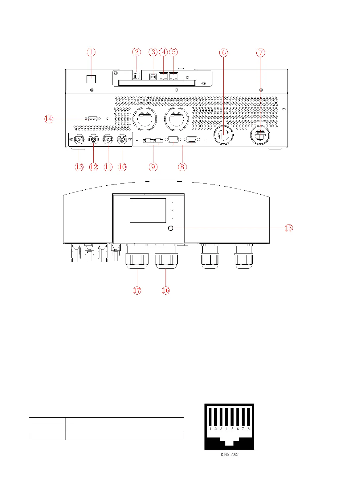
NOTE: The following picture is only a schematic diagram of the equipment .If the actual chassis does not
conform to the schematic due to a structural upgrade, it is subject to prior notice.
1: Remote LCD module communication port 2: Generator dry contact
3: USB port 4: RS485 port/CAN port
5: RS232 port 6: Battery positive
7: Battery negative 8:
Parallel port
9:
Current sharing port 10: PV1 negative connector
11: PV1 positive connector 12: PV2 negative connector
13: PV2 positive connector 14: WIFI port
15:
Power on/off switch 16:AC input connector
17:AC output connector
Note: RS485,CAN communication share the same port ,so it can’t be used at the same time.
Communication port definition:
RS232 1:RXD , 2:TXD,8:GND
RS485 6:485-B ,7.485-A
CAN
3:CAN-H,5:CAN-L