6 Ultrasound Controller Manual
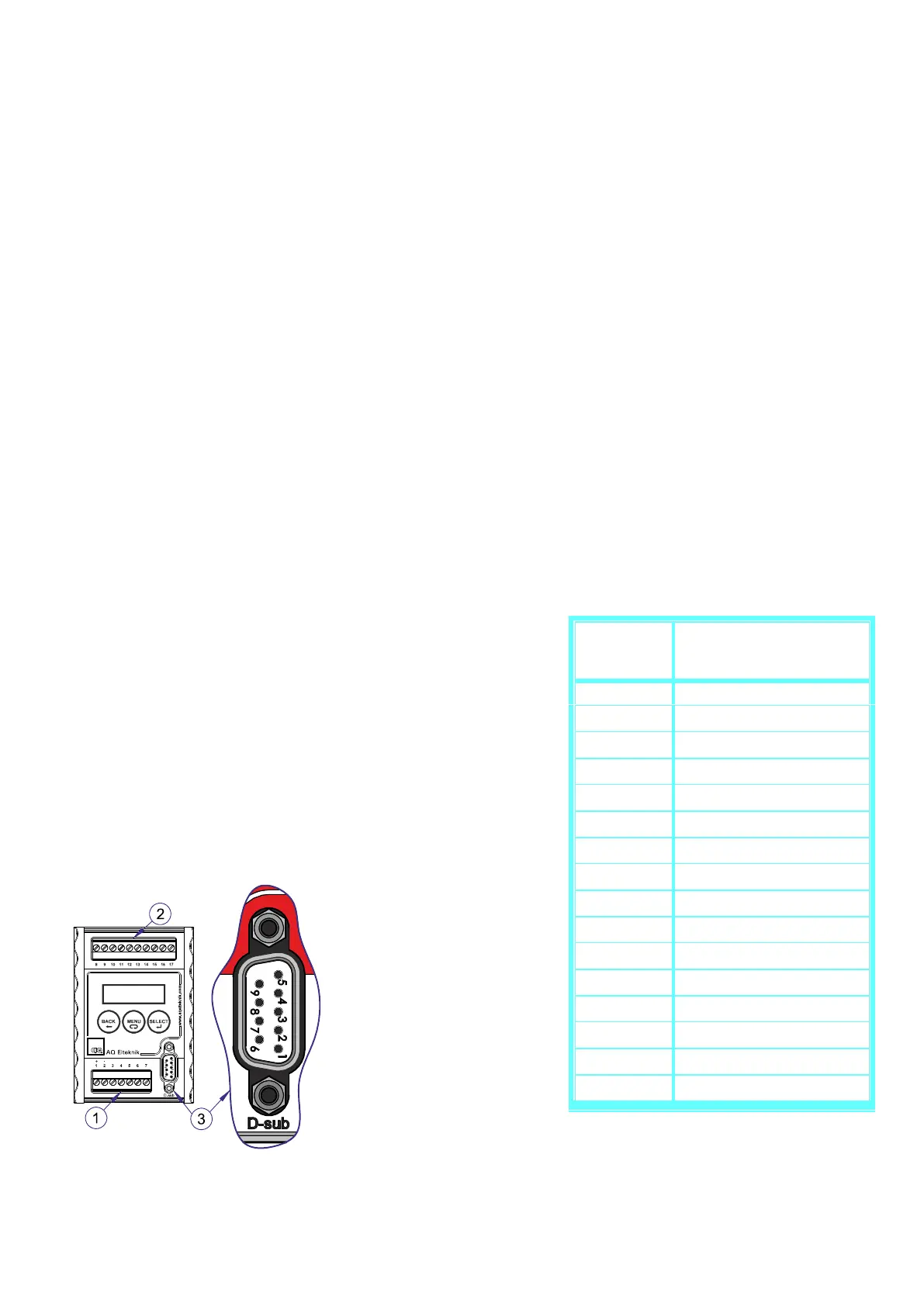
1 Terminal
2 Terminal (for Sensors)
3 D-sub
2. Introduction
Ultrasound Controller
Ultrasound Controller uses ultrasound to make measurements. It can detect bubbles in flowing
liquid or it can detect presence of liquid behind a container wall or it can measure continuous
liquid level. The Ultrasound Controller has four different modes of operation:
Air Sensor mode: The Air Sensor monitors the presence of gas or particles in flowing liquid. The
Air Sensor is very reliable and easy to use. Two Air Sensors can be connected to one
Ultrasound Controller.
Level Switch mode: The Level Switch is a small sensor which attached to the outside of the
container can sense the presence of liquid inside the container without making hole in the
container. Four Level Switches can be connected to one Ultrasound Controller.
Level Sensor mode: Continuous liquid level is measured with a Level Switch attached under the
container bottom (no hole in the container). High accuracy is achieved with a second Level
Switch measuring liquid sound velocity. Two levels can be measured with one Ultrasound
Controller.
Gel Sensor mode: The Level Switch attached to the outside of the container can sense the
presence of gel inside the container without making hole in the container. Four single gel-
levels can be measured with one Ultrasound Controller.
Installing the Ultrasound Controller D72 and G72
The Ultrasound Controller D72 should be protected from
dust and water. It is made to be attached to a DIN-rail, to
which it snaps easily and can be removed by pushing up
and bending the top out. Usually it is installed in a cabinet.
The green connector terminals can be removed by pulling
the connector out.
The Ultrasound Controller should be installed in accordance
with national regulations. A person with the required
knowledge should perform the installation.

 Loading...