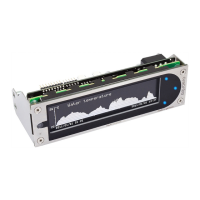
AQUAERO 5 / AQUAERO 6
Pin 3 GND
Pin 4 +5 V
4.3.
4.3.4.3.
4.3. Connector “Fan 1/2/3/4”
Connector “Fan 1/2/3/4”Connector “Fan 1/2/3/4”
Connector “Fan 1/2/3/4”
Voltage regulated fan outputs with speed signal processing.
aquaero 5:
Maximum output power is 19.8 W (1.65 A at 12 V) for each channel. Maximum
power is dynamically limited through temperature monitoring and will decrease
considerably at lower output voltages. In case an output amplifier temperature
rises to ca. 95 °C, the output is set to 100 % power. After cooling down to ca.
70 °C, normal operation will resume. If the temperature rises to ca. 100 °C, the
output will be permanently disabled. To reactivate the output, the aquaero (or
the complete PC) has to be disconnected from power for a short period of time.
Despite this overload protection, the fan outputs are not short-circuit proof!
Special feature “Fan 4”:
Special feature “Fan 4”:Special feature “Fan 4”:
Special feature “Fan 4”: This connector can be used for conventional fans or
→ →PWM controlled fans. For PWM fans, select “Outputs” “Fans” “Fan 4” from
the menu and set “Control mode” to “PWM controlled”.
aquaero 6:
Maximum current is 2.5 A per output independent of output voltage, resulting in
a maximum power of 30 W at 12 V. Outputs will be switched off if amplifier
temperatures reach a critical level and will automatically be reactivated when
cooled down. If an output current of 3 A is exceeded, the output will be perma-
nently disabled. To reactivate the output, the aquaero (or the complete PC) has
to be disconnected from power for a short period of time. The fan outputs are
short-circuit proof.
All fan connectors can be used for conventional fans or PWM controlled fans.
→ →For PWM fans, select “Outputs” “Fans” “Fan 1-4” from the menu and set
“Control mode” to “PWM controlled”.
Pin assignment: Pin 1: GND
Pin 2: 0-12 V
Pin 3: Speed signal
Pin 4: PWM signal (aquaero 5: Fan 4 only)
4.4.
4.4.4.4.
4.4. Connector “PWM 1/2”
Connector “PWM 1/2”Connector “PWM 1/2”
Connector “PWM 1/2”
Pulse width modulated 12 V outputs, maximum current load 1 A, carrier frequency
15 kHz. Suitable for example for 12 V LEDs, not compatible with PWM fans or
pumps.
Pin assignment: Pin 1: VCC
Pin 2: GND
Compatible products:
- 8 - Aqua Computer GmbH & Co. KG © 2014-2019
Gelliehäuser Str. 1, 37130 Gleichen

 Loading...