6
ISOBUS
PLUG
HYDRAULIC
CONTROL
UNIT
AUXILIARY
INPUT PLUG
10 m
3 m
3 m
3 m
1 m 0,2 m
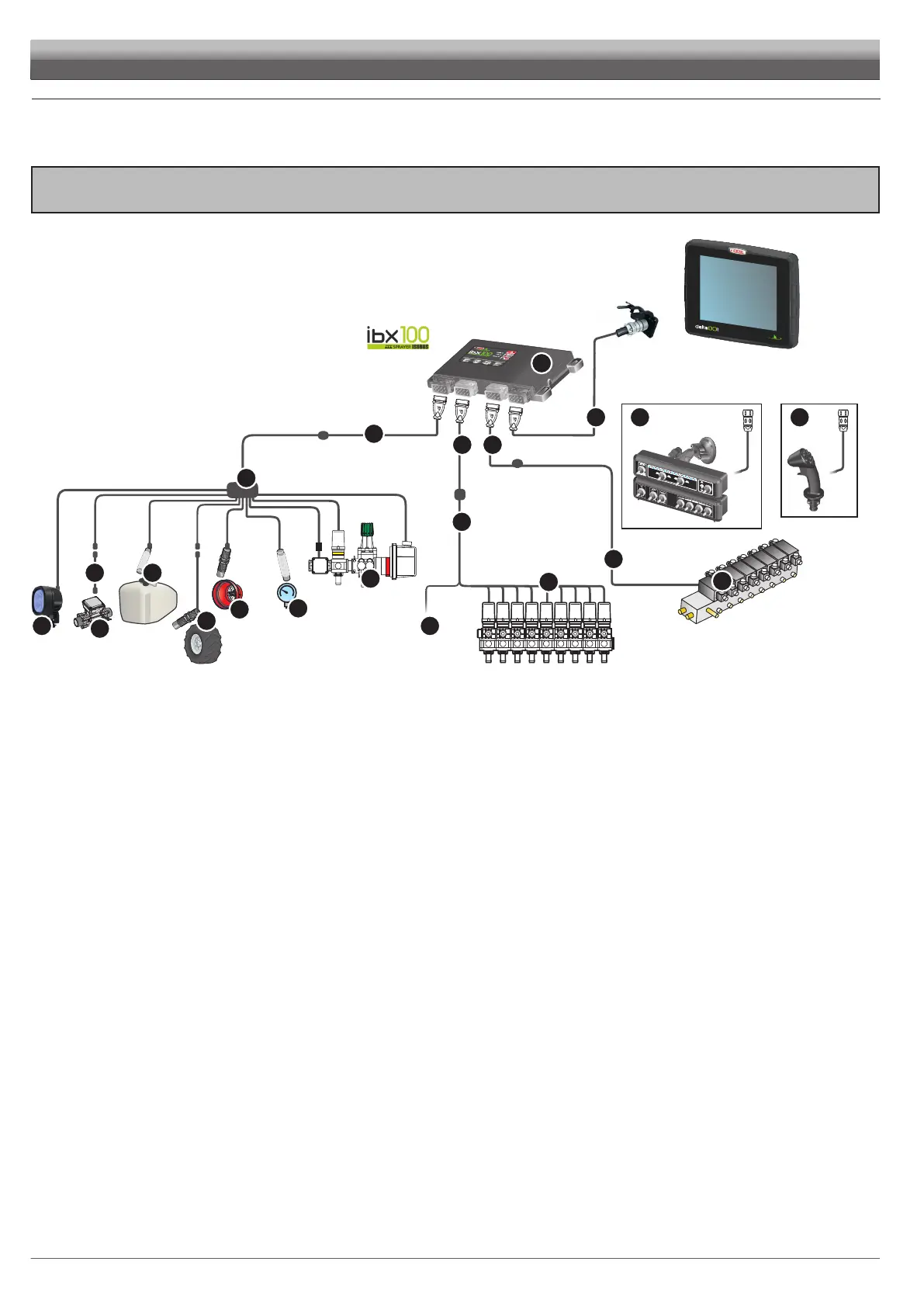
INSTALLATION
> > > 5.1 System recommended composition
INSTALLATION DIAGRAM
VERSION FOR SECTION VALVES AND HYDRAULIC CONTROLS
To connect all parts of the system correctly, make sure to use the proper connection cables.
Consider any variants depending on system type.
1 2 3
4
10
11
12 12
14
13
20
18
15
16
17
5
6
8
9
7
FENCE
19
Legend:
1
2
3
4
5
6
7
8 Control unit with flowmeter
9 Control unit (section valves)
10
11
12
13
14 Hydraulic control unit
15 Pressure sensor
16 RPM sensor
17 Filling flowmeter
18 Level sensor
19 Seletron Custom Connector for Fence End Nozzles
20 Boom lighting / flashing light
 Loading...