5
ISOBUS
PLUG
HYDRAULIC
CONTROL
UNIT
AUXILIARY
INPUT PLUG
TERMINAL
ERROR
IN OUT
ERROR
IN OUT
INSTALLATION
CONTINUES > > >
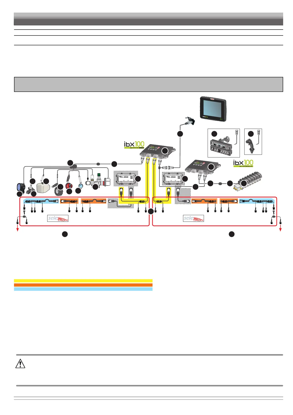
5 POSITION ON FARMING MACHINE
5.1
To connect all parts of the system correctly, make sure to use the proper connection cables.
Consider all possible variants:
• type of system,
• type of Seletron units connected (single, twin or fourfold)
• number of nozzles per mechanical arm (of spraying boom)
Legend:
1
2
3
4
5
6
7 Control unit with flowmeter
8 Seletron cables:
central cables
extension cables
termination cables
9 Battery Booster
10
11
12
13 Pressure sensor
14 RPM sensor
15 Filling flowmeter
16 Level sensor
17
18
19
20 Hydraulic control unit
21 Seletron for Fence / Buffer end nozzles
22 Boom lighting / flashing light
INSTALLATION DIAGRAM
VERSION FOR SELETRON AND HYDRAULIC CONTROLS
LINE 2
FENCE / BUFFER
LINE 1
1 2 3
4
10
17
18
19
11
20
21
21
12 16
13
14
15
22
5
6
7
9 9
8
FENCE / BUFFER
 Loading...