35
SP243A
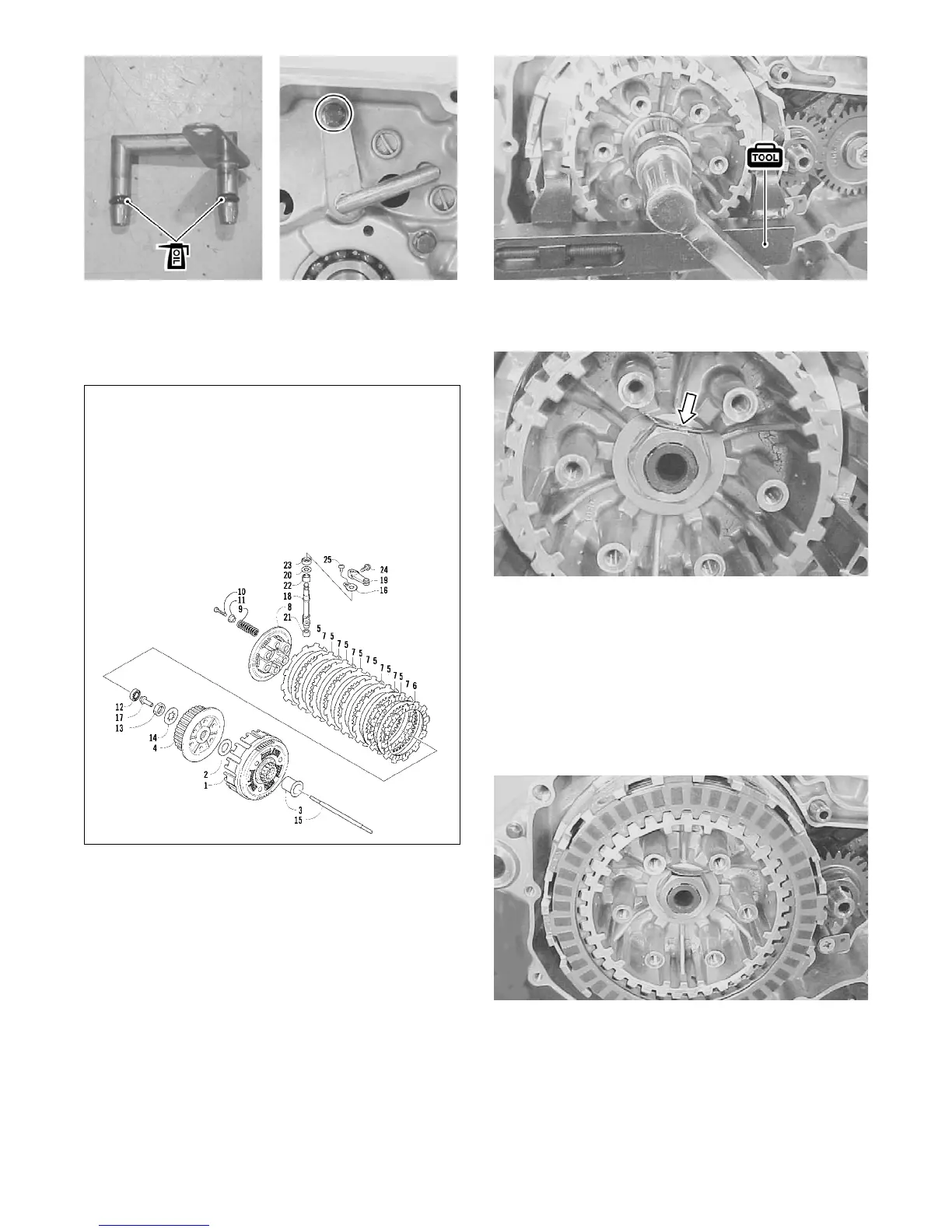
12. Install the spacer (3), primary driven gear assembly
(1), washer (2), clutch sleeve hub (4), lock washer
(14), and clutch sleeve hub nut (13) on the drivesh-
aft.
0739-225
13. Using the special holding tool, hold the clutch sleeve
hub and tighten the clutch sleeve hub nut to specifi-
cations.
SP245
14. Bend the washer over securely engaging the flat of
the nut.
SP246
15. Install the drive and driven plates one by one into the
clutch hub sleeve in the prescribed order.
NOTE: Be sure to install the drive plate with the
inside diameter of 122.5 mm (4.82 in.) first. Two dif-
ferent types of drive plates are used. They are the
one with the 122.5 mm (4.82 in.) inside diameter
and seven with an inside diameter of 116.0 mm (4.5
in.).
SP247
16. Referring to the illustration, install the clutch push
rod (15) and clutch release pin (17) and bearing (12);
then install the pressure disc (8) and tighten the
clutch spring set bolts in stages using the illustrated
pattern.
KEY
1. Primary Driven Gear
2. Washer
3. Spacer
4. Sleeve Hub
5. Drive Plate #1
6. Drive Plate #2
7. Driven Plate
8. Pressure Disc
9. Spring
10. Bolt
11. Washer
12. Bearing
13. Nut
14. Lock Washer
15. Push Rod
16. Retainer
17. Release Pin
18. Camshaft
19. Release Arm
20. Washer
21. Bearing
22. Bearing
23. Seal
24. Cap Screw
25. Camshaft Stopper
 Loading...