109
FS235A
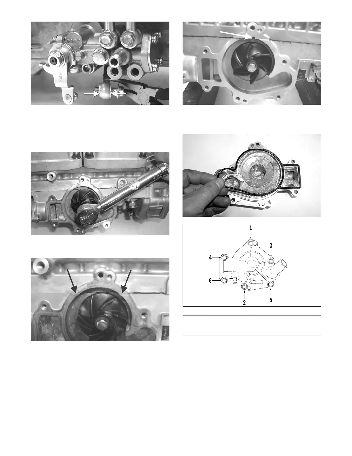
10. Place the impeller into position and secure with a cap
screw and washer. Be sure the rubber side of the
washer is lubricated with a fine coat of oil and
directed towards the impeller. Apply blue Loctite
#243 to the threads of the cap screw and tighten to
108 in.-lb.
FC132
11. Apply sealant to the crankcase seam; then install the
alignment pins into the crankcase (if removed).
FC133A
NOTE: Do not allow sealant into the breather hole
in the crankcase. If sealant gets into the hole, carefully
remove before proceeding.
FC072B
12. Position the O-ring into the water pump cover; then
install the cover. Install the cap screws; then using
the pattern shown, tighten to 96 in.-lb.
FC134
0742-304
Water Pump - 6000
DISASSEMBLING
NOTE: The engine must be removed for this proce-
dure.
NOTE: A bleed hole is located in the crankcase
beneath the water pump housing. If any signs of cool-
ant or oil leakage from the bleed hole exist, the seals
must be replaced.