112
CWI-096
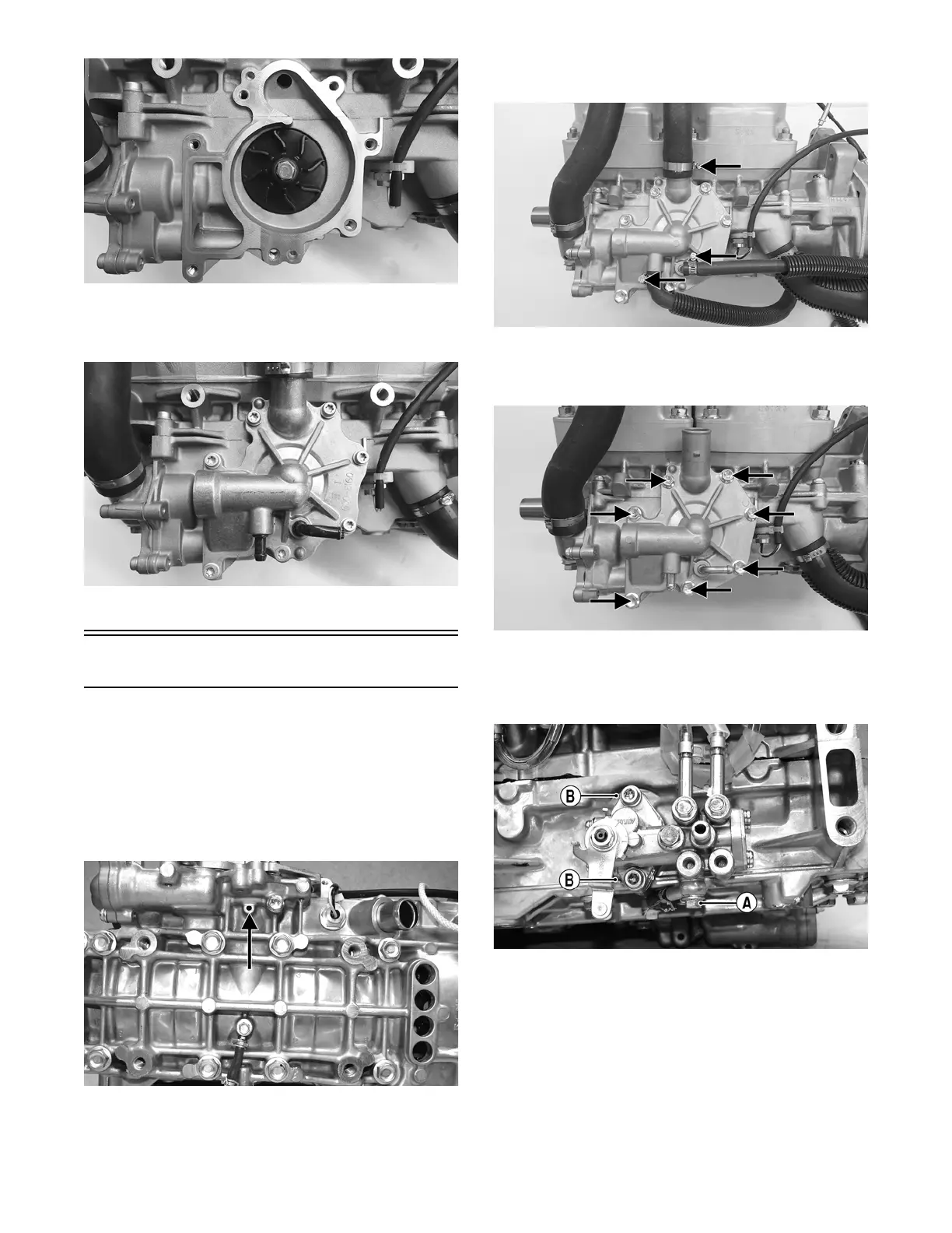
9. Position the O-ring into the water pump cover; then
install the cover. Install the cap screws; then tighten
to 96 in.-lb using a crisscross pattern.
CWI-095
10. Secure the hoses to the water pump cover.
Water Pump - 8000
DISASSEMBLING
NOTE: The engine must be removed for this proce-
dure.
NOTE: A bleed hole is located in the crankcase
beneath the water pump housing. If any signs of cool-
ant leakage from the bleed hole exist, the water pump
seals must be replaced.
FS219A
NOTE: When servicing the water pump, use Water
Pump Bearing and Seal Tool Kit and Oil Seal Protec-
tor Tool.
1. Loosen the clamps securing the coolant hoses to the
water pump; then remove the hoses.
XM114A
2. Remove the seven cap screws securing the water
pump cover; then remove the cover and account for
the O-ring seal and two dowel pins.
XM113A
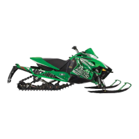
3. Remove the cap screw (A) securing the lower check
valve to the oil pump and account for the two gas-
kets; then remove the two cap screws (B) securing
the oil pump to the engine. Remove the pump.
FS220A
NOTE: Leave the two upper check valves secured to
the pump.