152
Testing Speedometer
Sensor
NOTE: The following test should be made using
MaxiClips and the Fluke Model 77 Multimeter set to
the DC Volt scale.
NOTE: Prior to testing the sensor, inspect the
three-wire connector on the sensor harness for con-
tamination, broken pins, and/or corrosion. With the
engine running, note that a power supply of 10.8-14.4
DC volts exists at the main harness/speedometer con-
nector.
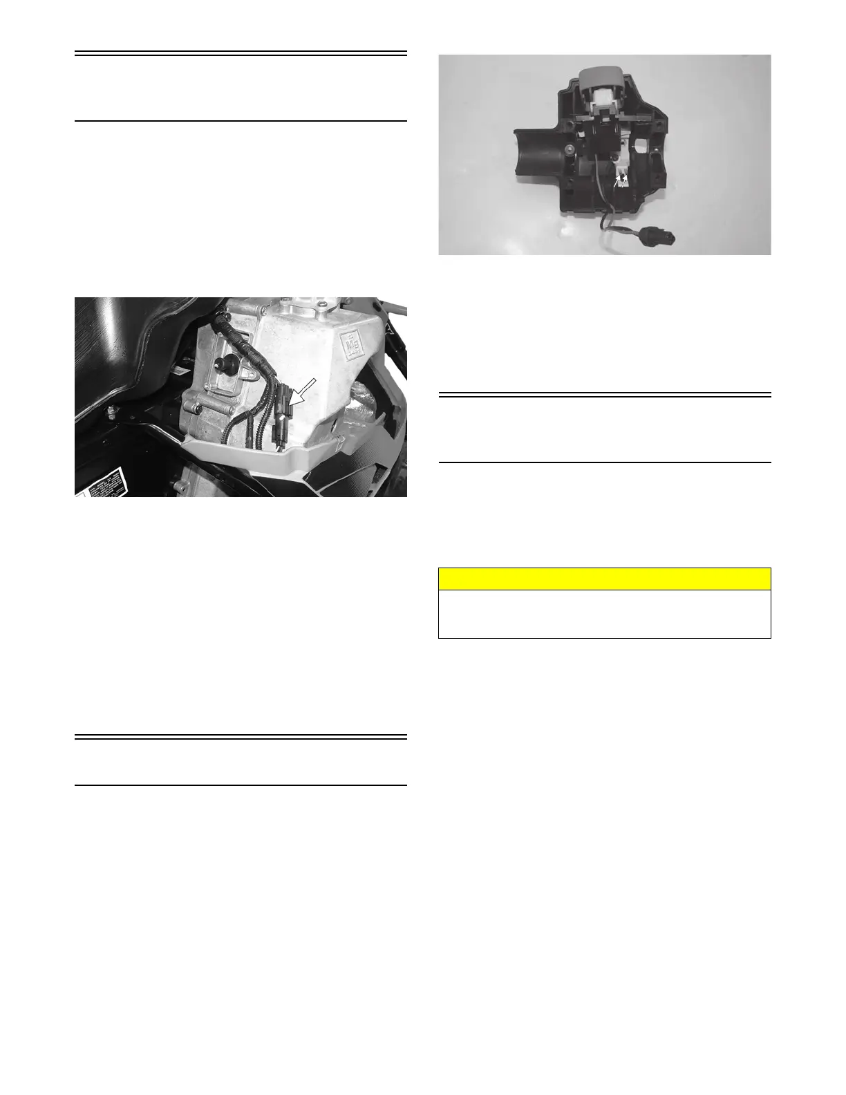
XM208A
1. Elevate the rear of the snowmobile onto a suitable
safety stand.
2. Set the meter selector to the DC Voltage position.
3. At the sensor side of the plug-in, connect the red
MaxiClip and meter lead to the white/orange lead;
then connect the black MaxiClip and meter lead to
the black lead.
4. Connect a positive 12-volt DC power supply to the
red/blue wire; then connect a negative cable to the
black wire from the main harness side of the plug-in.
5. Rotate the driven clutch. The meter must read 0 volts
and 12 volts alternately.
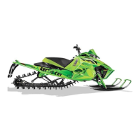
Testing Shift Switch
NOTE: The switch is located on the right-side han-
dlebar control. To access the switch, the control
assembly must be disassembled.
1. Disconnect the two-wire connector from the handle-
bar control.
2. Connect one ohmmeter lead to one pin; then connect
the other ohmmeter lead to the other pin.
PC253B
3. With the reverse button pressed in, the meter must
read less than 1 ohm of resistance. With the reverse
button released, the meter must read OL (infinite
resistance).
NOTE: If the meter does not read as specified in
either test, the switch is defective and must be
replaced.
Testing
Servomotor/Potentiometer
SERVOMOTOR
NOTE: A 12-volt battery and test leads will be
needed for this test.
1. Remove the servomotor from the snowmobile.
2. Contact the red/black servo terminal with the battery
positive lead; then contact the black/red servo termi-
nal with the battery negative lead.
3. The servo should rotate when the negative lead con-
tacts the black/red terminal. Note the direction of
rotation.
4. Reverse the connections on the servo terminals: pos-
itive lead to black/red and negative lead to red/black.
The servomotor should rotate in the opposite direc-
tion.
5. Install the servomotor.
NOTE: If the servo operates correctly in the above
test but fails to operate when connected to the
ECM/regulator/rectifier at the designated RPM, pro-
ceed to Potentiometer test.
POTENTIOMETER
NOTE: The following test should be made using
MaxiClips and the Fluke Model 77 Multimeter set to
the ohms scale.
1. Remove the servomotor from the snowmobile.
CAUTION
Care must be taken not to contact the servo yellow,
orange, or black/white terminals, or damage to the
potentiometer circuit will result.