140
1. Test between the two orange wires in the four-prong
connector from the magneto.
2. Resistance must be 1.52-2.28 ohms.
Injection Coil
1. Test between the two blue/white leads in the
four-prong connector harness from the magneto.
2. Resistance must be 15.2-22.8 ohms.
Lighting Coil
1. Disconnect the main harness from the magneto.
2. Connect the two meter leads to each of the yellow
leads in the connector from the engine.
3. Resistance must be 0.08-0.12 ohm.
Ignition Timing Sensor (4000)
1. Disconnect timing sensors 1 and 2 (green/white and
brown/green) from the main harness.
2. Connect the meter leads to the sensor leads.
3. Resistance must be 80.8-121 ohms.
Ignition Timing Sensor (6000/8000)
1. Disconnect timing sensors 1 and 2 (green/white and
brown/green) from the main harness.
2. Connect the meter leads to the sensor leads.
3. Resistance must be 148-222 ohms.
Ignition Coil (Primary)
1. Disconnect the double wire plug from the main har-
ness to the ignition coil.
2. Connect the red meter lead to the orange/black
(4000) or black/white (6000/8000) lead; then con-
nect the black meter lead to the orange/red (4000) or
white/blue (6000/8000) lead.
3. Ignition coil primary resistance must be between
0.24-0.36 ohm.
Ignition Coil (Secondary) (4000)
1. Remove the spark-plug caps from the high tension
wires.
2. Connect the red meter lead to one high tension wire;
then connect the black meter lead to ground.
3. Resistance must be 6800-10,200 ohms.
Ignition Coil (Secondary) (6000/8000)
1. Remove the spark-plug caps from the high tension
wires.
2. Connect the red meter lead to one high tension wire;
then connect the black meter lead to ground.
3. Resistance must be 5040-7560 ohms.
Spark-Plug Cap
1. Remove the spark-plug caps from the high tension
wires.
2. In turn on each cap, touch a tester lead to each end of
the spark-plug cap.
3. Resistance must be 4000-6000 ohms.
Ignition Switch
NOTE: The console must be removed to access the
ignition switch.
1. Remove the main wiring harness connectors from
the ignition switch.
2. Rotate the key to the OFF position.
3. Resistance must read less than 1 ohm between the
ignition switch terminals.
4. Rotate the key to the RUN position. The meter must
read OL (infinite resistance).
Fuel Injector
1. Disconnect the fuel injector wiring harness; then set
the meter to the OHMS position.
2. Test between the two injector terminals. Resistance
must be 10-14 ohms (4000/8000) or 11.4-12.6 ohms
(6000).
3. If not within specifications, replace the injector.
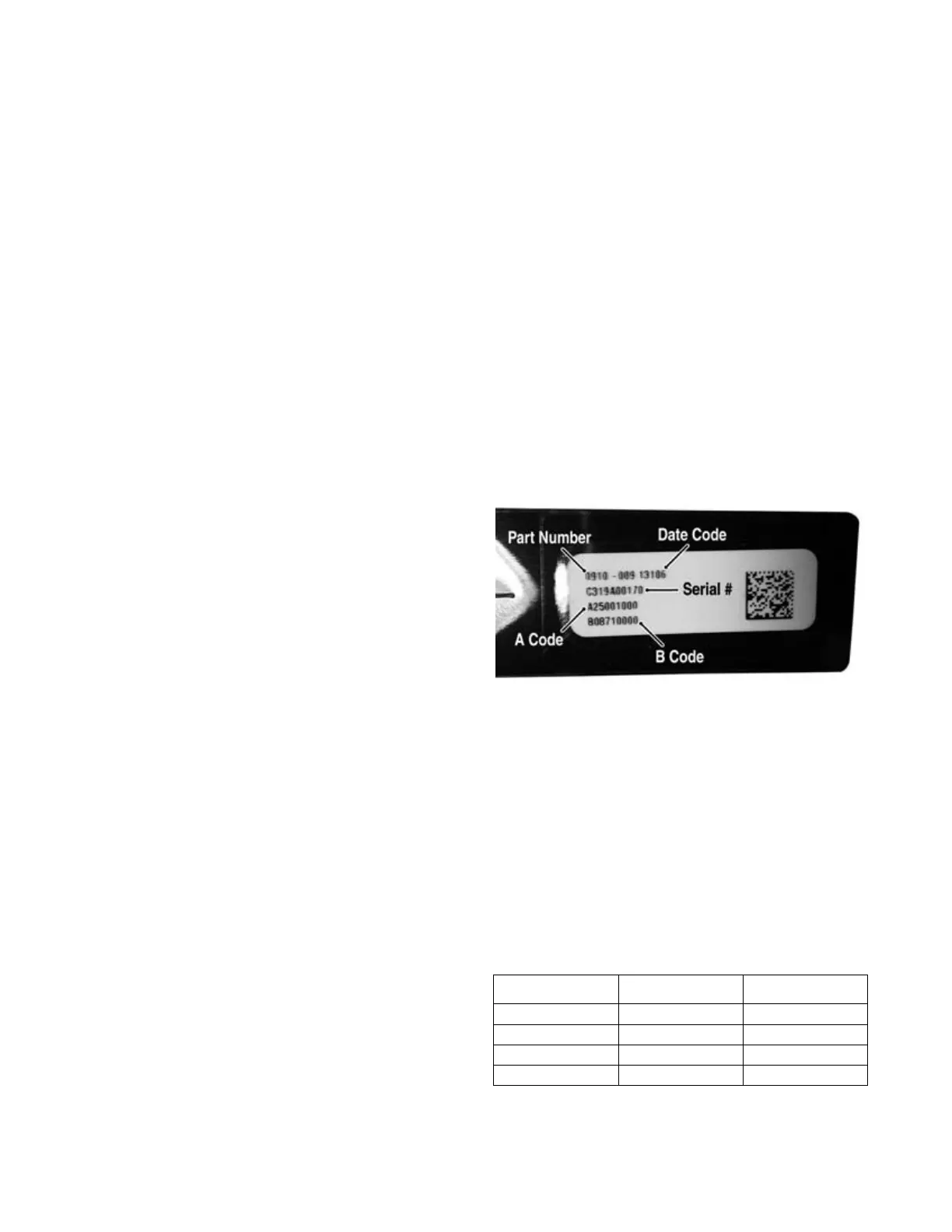
NOTE: When replacing the injector on the 6000, the
A and B codes must be entered using the CATT II Tool.
SNO-1235A
Exhaust Temperature Sensor
1. Disconnect the sensor harness; then remove the sen-
sor from the exhaust pipe.
2. Suspend the sensor (only up to the threads) in a con-
tainer filled with automatic transmission oil; then
slowly heat the oil on a hot plate.
3. Using a fluid thermometer, closely monitor the oil
temperature, and using a digital multimeter with the
leads connected to the sensor leads, observe the
resistance reading.
4. The sensor must read as shown (see chart).
Coolant Temperature Sensor
1. Disconnect the coolant temperature sensor wiring
harness from the main harness.
° F ° C ohms
77 25 219.6
122 50 238.5
212 100 275.9
302 150 312.7
 Loading...