172
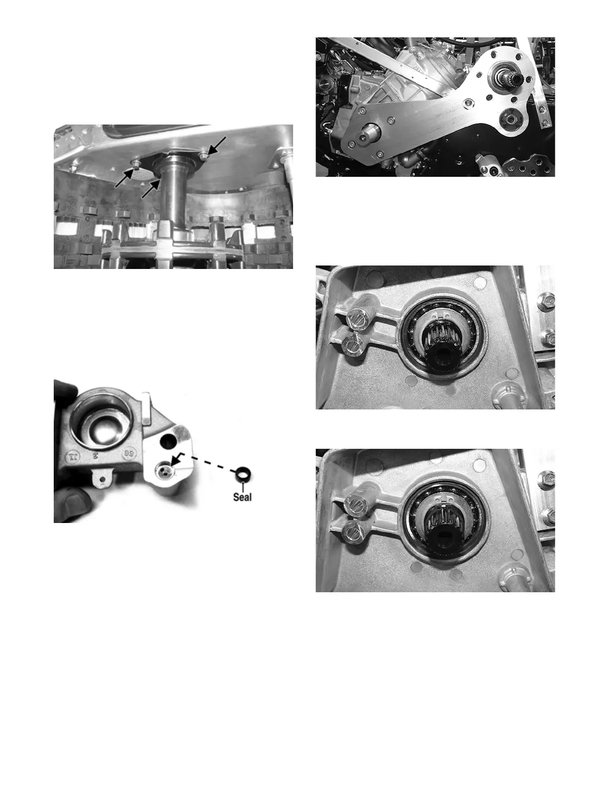
2. Place the driveshaft/drive sprocket assembly into the
tunnel brake-end first; then into the chain case drive-
shaft bearing.
3. Install the inner brake caliper assembly and secure
with three cap screws and the retaining ring. Tight-
ened cap screws (threads coated with blue Loctite
#243) securely.
PC148A
NOTE: If the brake caliper was split, proceed to
step 4. If not, proceed to step 6.
4. Install the brake disc and secure with the retaining
ring.
5. Making sure the seal is correctly installed in the
outer brake caliper, install on the inner caliper and
secure with two cap screws. Tighten to 25 ft-lb.
PC173A
6. Install the skid frame (see the Suspension section).
7. Install the brake shield and left-side footrest. Tighten
the cover cap screws to 8 ft-lb.
8. Install the driven shaft w/mount plate from the
left-side; then secure the PTO-side engine mounting
plate to the crankcase and the chassis with the exist-
ing cap screws (coated with blue Loctite #243) and
one washer. Tighten to 30 ft-lb.
XM391
9. Install the drive clutch and tighten the clutch cap
screw w/washer to 51 ft-lb; then install the driven
clutch and drive belt. Tighten to 20 ft-lb.
10. Install the existing washers; then press in on the
driven shaft and secure the shaft using the existing
washer and snap ring.
XM388
11. Install the black snap ring onto the inner snap ring
groove in the driven shaft.
XM389
12. Install the sprockets and chain onto the driveshaft
and driven shaft and secure using the existing snap
rings.
 Loading...