53
5. Install the PTO-side chassis support to the shock
mount bracket and chassis. Secure with the cap
screws and carriage bolt nut. Tighten the rear chassis
cap screw to 25 ft-lb, the carriage bolt nut to 12 ft-lb,
and the front shock mount cap screws to 12 ft-lb.
6. Install the torx-head screw to secure the front belt
guard to the skid plate. Tighten securely.
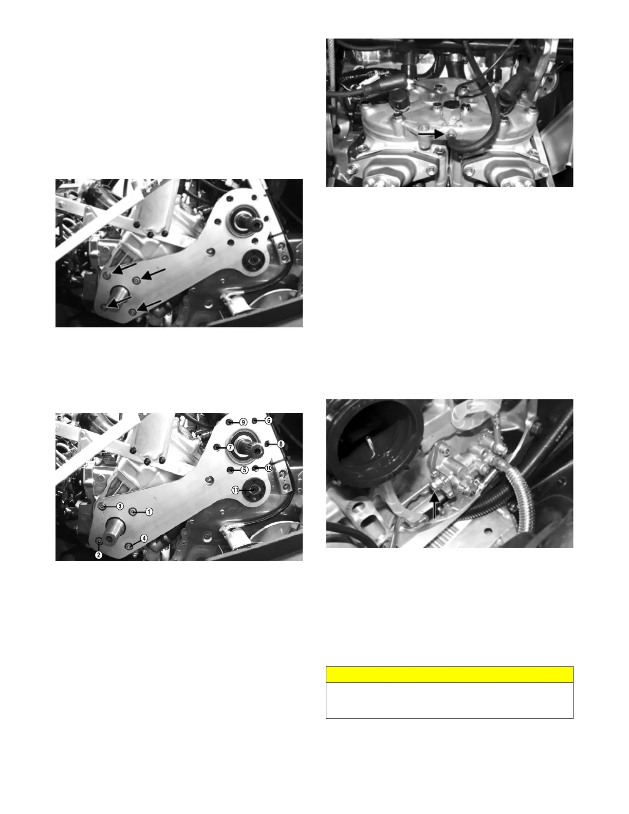
7. Install eleven new “patch-lock” screws securing the
PTO-side engine mounting plate starting with the
four plate-to-engine screws. Finger-tighten only at
this time.
PC180A
NOTE: Make sure to install the spring washer
between the rear mount and the tunnel.
8. From step 7, tighten the four front screws to 30 ft-lb,
the six top rear screws to 14 ft-lb, and the lower rear
screw to 25 ft-lb using the following sequence.
PC180B
9. Tighten the cap screw and lock nuts (from step 4) to
25 ft-lb.
10. Install the access panel to the center belly and chassis
and secure using the torx-head screws. Tighten
securely.
11. Tighten the cap screws (from step 3) to 25 ft-lb.
12. Connect the knock sensor and coolant temperature
sensor connectors; then install the spark plug caps.
Secure the coolant temperature sensor connector
with a cable tie.
13. Install the cylinder head vent hose.
PC178B
14. Place the recoil starter into position and secure with
the cap screws. Tighten in a crisscross pattern to 96
in.-lb.
15. Before connecting the wiring harness plug-ins, clean
the connectors and apply Dielectric Grease to the
seal; then connect all harness connectors making
sure all wiring and coolant hoses are routed properly
as noted in removing. Install the main harness wrap.
NOTE: Use cable ties to secure the wiring harnesses
as necessary.
16. Connect the oil hose to the oil pump. Secure with the
clamp.
NOTE: After securing the oil hose to the oil pump,
remove the bleed screw to allow any air in the
hose/pump to be released.
PC179A
17. Connect the MAG-side throttle body coolant hose;
then secure with a clamp.
18. Connect the TPS; then lower the throttle body
assembly into the engine compartment.
19. Place the throttle body assembly into position and
secure with the flange clamps; then connect the gas-
line hose to the throttle body assembly and tighten
the clamp securely.
20. Connect the PTO-side throttle body coolant hose;
then secure with a clamp.
21. Fill the cooling system (see Liquid Cooling System
in the Engine-Related Items section).
CAUTION
When installing the throttle bodies, make sure the gas-
line hose is properly routed to avoid premature wear
and/or contact with exhaust components.
 Loading...