59
FC022
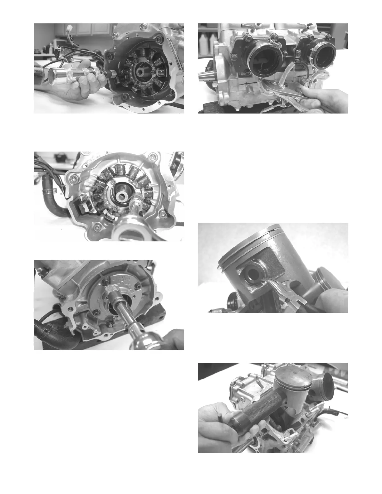
5. Remove the Allen-head cap screws securing the sta-
tor to the stator plate. Move the stator to the side to
access the Phillips-head cap screw securing the stator
lead wire; then remove the cap screw.
FC018
6. Remove the stator plate from the engine.
FC021
NOTE: The stator plate screws had Loctite applied
to the threads during assembly. Using an impact
driver, apply a sharp blow to the head of each screw
to break the Loctite loose before removal.
7. Remove the spark plugs.
8. Remove the cap screws with O-rings securing the
cylinder head; then separate from the cylinders.
Account for the O-rings.
9. Remove the oil-injection hose from each flange and
the crankcase nozzle.
FC026
NOTE: When removing the cylinders, place the
engine on its intake flanges on a drain tray to allow
residual coolant to drain from the cylinder/crankcase
water jacket.
10. Remove the eight nuts securing the cylinders to the
crankcase; then using a rubber hammer, gently tap
the cylinders and remove from the crankcase by lift-
ing them straight up off their studs. Account for gas-
ket(s) and any alignment pins.
11. Remove the PTO-side piston-pin circlip from the
PTO-side piston; then remove the MAG-side pis-
ton-pin circlip from the MAG-side piston. Discard
the circlips.
CM149
12. Using Piston Pin Puller, remove the piston pins from
both pistons.
NOTE: For proper assembly, keep all MAG-side
components and all PTO-side components separated.
Assemble them on their proper sides.
FC029