95
CWI-090
CWI-089
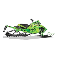
3. Place the bore gauge in the cylinder and measure
each cylinder in locations from front to back and side
to side top and bottom of the cylinder for a total of
four readings. The difference (clearance) must be
within 0.0031-0.0041 in.
CWI-087
CWI-086
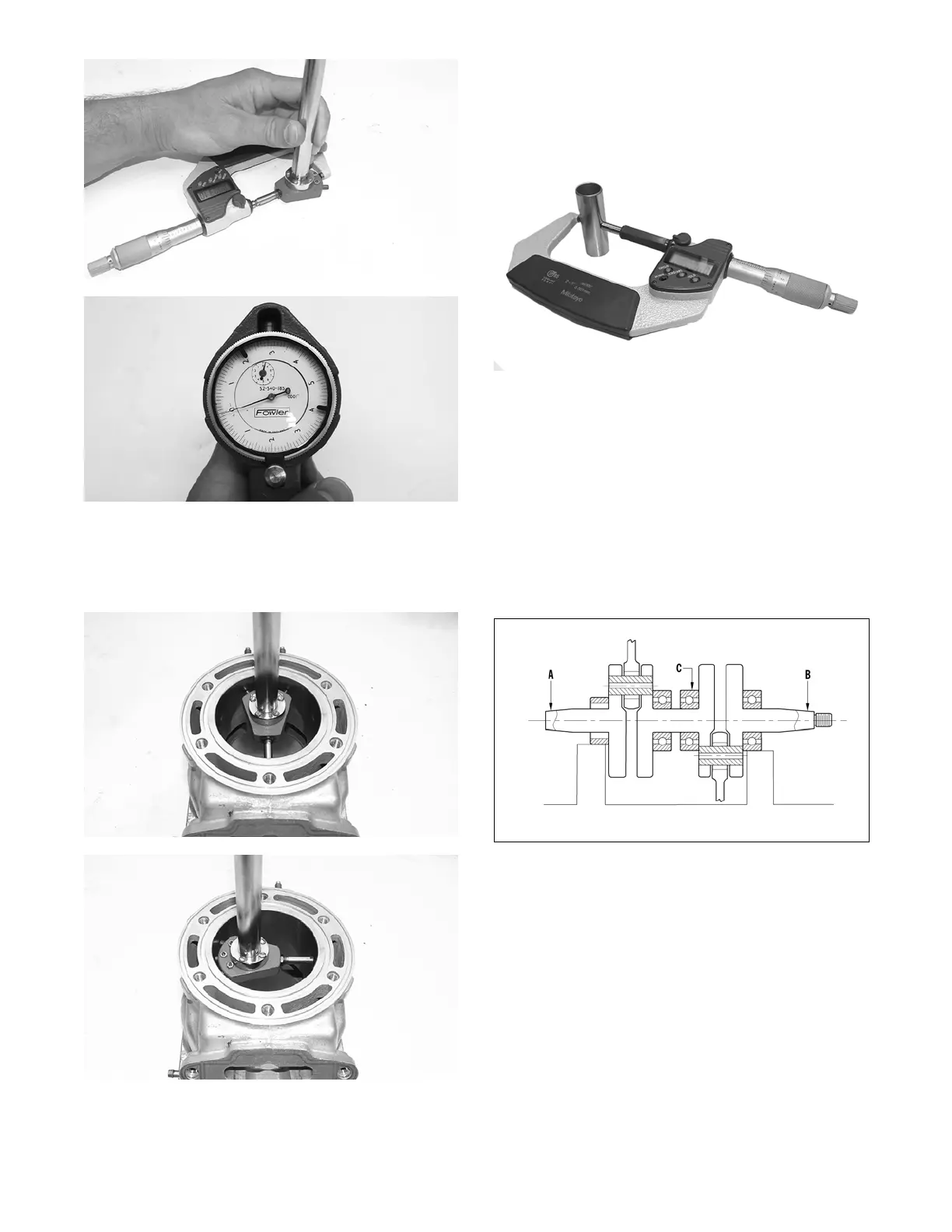
PISTON PIN
Measure the piston pin diameter at each end and in the
center. Acceptable piston pin measurement must be
within 0.8659-0.8661 in. If any measurement varies by
more than 0.001 in., the piston pin and bearing must be
replaced as a set.
CWI-079
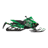
CRANKSHAFT RUNOUT
1. Using the V Blocks, support the crankshaft on the
surface plate.
NOTE: The V blocks should support the crankshaft
on the outer bearings.
2. Mount a dial indicator and base on the surface plate.
Position the indicator contact point against the crank-
shaft location point A (PTO-end) from the crankshaft
end. Zero the indicator and rotate the crankshaft
slowly. Note the amount of crankshaft runout (total
indicator reading).
0742-727
NOTE: For runout location point specifications, see
Crankshaft Runout/Repair Specifications in the Gen-
eral Information section of this manual.
3. Position the indicator contact point against the crank-
shaft location point B (MAG-end) from the crank-
shaft end. Zero the indicator and rotate the
crankshaft slowly. Note the amount of crankshaft
runout (total indicator reading).