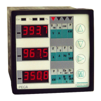
PECA 30 / 30 E : Accessible functions during the measurement
43
ARDETEM
See capture functions Nr 1 page 16
Back to the measurement, with modifications validation
ALARMS AND ERRORS MEASUREMENT
• MEASUREMENT ALARMS :
For each input V1,V2,V3,I1,I2,I3 corresponds an alarm, witch set off in case of overflow or line break.
The alarms can be enable or no (see p.23).
The different alarms :
AL 1 : V1<10v or overflow (>20% range) AL 2 : V2<10v or overflow (>20% range)
AL 3 : V3<10v or overflow (>20% range) AL 4 : overflow on I1 (>50% range)
AL 5 : overflow on I2 (>50% range) AL 6 : overflow on I3 (>50% range)
AL 7 : mesh voltage unbalance >40% AL 8 : mesh currents unbalance >80%
AL 9 : simple voltages > mesh voltages
In case of alarm, the analyser displays « AL N » N is alarm number, the analog outputs overload like
programmed with the security type, the relays will be OFF if the security is high, and ON if the security is low.
• MEASUREMENT ERRORS :
In case of error, the « Ctrl » led in front panel blinks, so press the key :
and, after the version
number, the analyser displays the error number.
The different errors :
ERR 1 : RS485 wiring check the RS wiring, check the RS485 network polarity
(switch on the micro-switch behind the instrument), wire the
ground with the earth, and let a 50ms response time
between 2 Modbus communications.
ERR 2 : incorrect currents order Check the wiring,
ERR 3 : incorrect phases (voltage) order Check the wiring,
ERR 4 : current range overtaking the internal or external CT doesn’t fit, check the
programming,
ERR 5 : voltage range overtaking check the programming voltage,
ERR 6 : frequency over-range check the network frequency (45<F<65Hz)
ERR 7 : programming loss program a second time the analyser,
ERR 8 : calibration loss back to the factory.
WARNING : to display errors 2 and 3 the measurement alarms must be ON.
ANALYSER CYCLE TIME
Recapitulative table : (without communication and without optional board)
Network 4 wires 3wires single phase or
3-phase balanced
cycle time 360ms 325ms 180ms
For each harmonic (or THD) displayed or transmitted on a output, add 180ms by harmonic at the cycle time
of the above table.
Add in more the communication time for a Modbus board.
Maximum response time = 2 x cycle time.