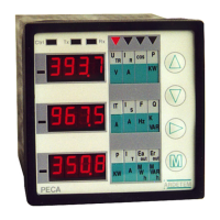
PECA30 / 30
E : general presentation
9
ARDETEM
CHAP 1 – GENERAL PRESENTATION
ANALYSER RECEIPT
Each alternating signals analyser is delivered with :
Its calibration form
this user manual
a Modbus / Jbus manual
2 stickers boards (for measurement units & symbols)
a documentation and a software for the data storage (in option)
a programming and visualization software of the measurements (in option)
Check if the analyser configuration (label on the housing top) corresponds to the order
Dismantle the metallic fixings on the sides
Insert the analyser in the cut-out, then put back the fixings and screw it.
STARTING
Connect the auxiliary supply.
Connect necessarily the earth wire (earth, terminal 12). It’s the guarantee for a good running in case of
electromagnetic disturbances by conduction or radiation.
At the start the analyser displays its type (PECA30, 30E...), and its program version. These data are
necessary for repair services.
Then the analyser displays the measurements with an initial configuration (except a specific order).
It advises strongly to program the analyser before to wire the input network.
Then connect all the signals : the measurement network and the inputs / outputs (refer to the wiring, in
page 44)
Solutions to some faults :
If the analyser isn’t lit : check the auxiliary supply,
check the back fusible
If the analyser doesn’t measure : check the voltage between the terminals 1 and 4 (L1and L4)
check the analyser programming (see page 40)
If the front panel Led « Ctrl » is lit : a wiring or programming mistake has been done.
(see the details page 43)
If the CT are reversed : the P and Q signs are reversed, a rectification is possible (page 19)
If the digital output doesn’t work, some helps are available (see in the Modbus manual)
The wiring of the inputs / outputs screening must be connected as shorter as possible to the terminal 12.