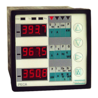
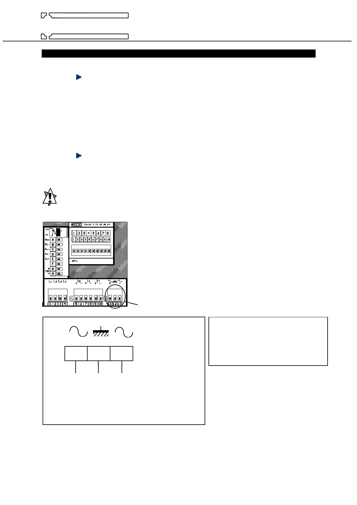
PECA 30 / 30E : wiring schema
44
ARDETEM
CHAP 4 - WIRING SCHEMA
WIRING ADVICE
The input network (UR , US , UT , IR , IS , IT) can transmit important parasitics which can disturb all
the analyse. To avoid this, it’s possible to increase the disturbance immunity with the rules bellow :
• Do not wired to close : the input electrical network from the PECA auxiliary supply wires.
• Do not wired to close : the input electrical network from the whole PECA output wires (analog
outputs, pulse outputs, relay outputs, digital output...)
• Use screen cables linked to the ground on each side, for all the PECA’s outputs.
• Do not forget to wire the PECA’s ground terminal on a “clean” ground.
AUXILIARY SUPPLY WIRING
In order that the analyser could operate, it must be supplied.
This supply has been chosen on the order ; check the value on the label situated on the top of the
analyser.
Do not forget to wire the CEM ground (Ground, terminal 12)
Auxiliary supply
11 12 13
P ground N Supply AC
+ ground - Supply DC
Note : For an AC supply, it’s possible to
wire indifferently the neutral and
the phase on the terminals 11 and 13.
For a DC supply, it’s possible
to wire indifferently the + and the – on
The terminals 11 and 13.
 Loading...