PECA 30 / 30 E : programming-configuration
24
ARDETEM
JbUS
brd.1
brd.2
Sor.1
brd.1
PULS
no
brd
99
JbUS
ESCL
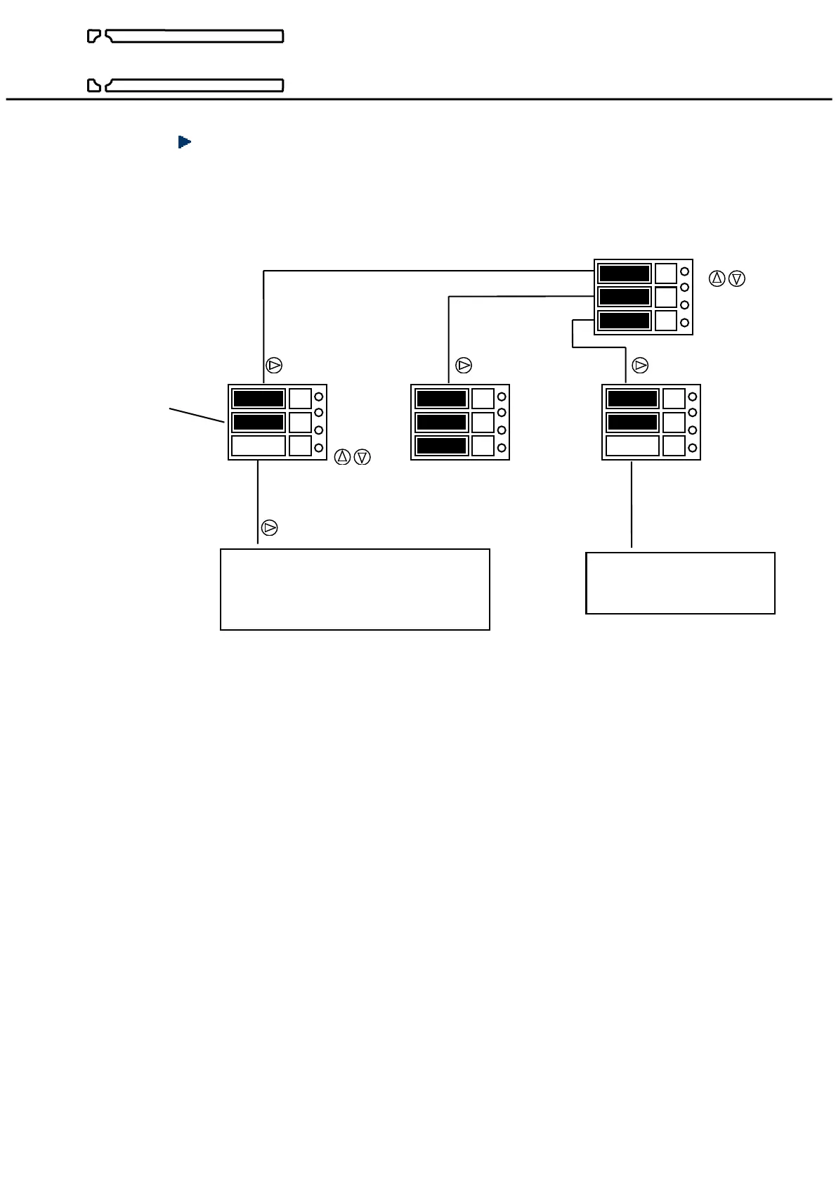
CONFIGURATION OF OPTIONAL BOARDS
PROGRAMMING MENU :
Example : board Nr1 = board of 3 pulse outputs board n°2 = option not available on PECA 30
board choice
board type
( details below) board Nr1 no board Modbus
Nr2 board
output choice
programming of the chosen output programming of the digital
Current output see page 31 output, Modbus / Jbus
Pulse output see page 28 see page 34
Alarm threshold see page 25
• TYPE OF BOARD :
The analyser displays « ALAr » : 3 alarms output type board (see p25)
The analyser displays « PULS » : 3 pulses output type board (see p28)
The analyser displays « AnA » : 3 analog outputs type board (current) (see p31)
The analyser displays « AnA.A » : 3 analog (current) outputs +2 alarms mixed type board (see p31 & 25)
The analyser displays « AnA.P » : 3 analog (current) outputs +2 pulses mixed type board (see p31 & 28)
• INPUT / OUTPUT BOARDS :
The board number corresponds to its position inside the analyser.
The boards have 3 inputs / outputs of the same time, except the mixed board (type « AnA.A » or « AnA.P »)
which have 2 outputs in more.
Type board « ALAr » : outputs 1,2,3 = threshold relays
Type board « PULS » : outputs 1,2,3 = pulse generator (on relay contact)
Type board « AnA » : outputs 1,2,3 = current outputs 4 20, 0 20, 0 10, 0 5, -20+20, -10+10 or -5+5mA
Type board « AnA.A » : outputs 1,2,3 = current outputs 4 20, 0 20, 0 10, 0 5, -20+20, -10+10 or -5+5mA
outputs 4,5 = threshold relays
Type board « AnA.P » : outputs 1,2,3 = current outputs 4 20, 0 20, 0 10, 0 5, -20+20, -10+10 or -5+5mA
outputs 4,5 = pulse generator (on relay contact)


 To Next Page