Argus E25 MOD II - Operating Instructions
connections at the termi-
on the PCB can cause the
on of individual compo-
or of the PCB.
Make sure all terminal con-
nections are assigned as
shown in the wiring diagram
supplied.
The cable glands are designed for Ø 9 to
16mm cables.
Connect the terminals to the power sup-
ply correctly and exactly as shown in the
wiring diagram and marked on the PCB.
When connecting to a single-phase or
three-phase AC supply for the motor, the
diode (D2) must be bridged:
(see Fig.)
:
When connecting to a DC supply, the
“AC bridge – BR1” must be
removed
(see
Fig.):
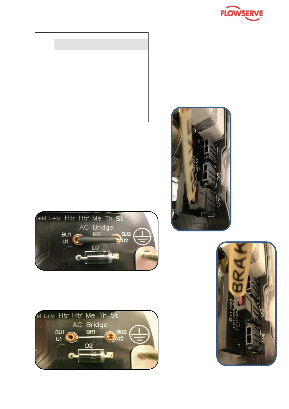
The brake must be connected according
to whether the
is AC (alter-
nating current) or DC (direct current):
- AC: Insert the “BRAKE” plug in the
AC
socket
- DC: Insert the “BRAKE” plug in the DC
socket
See illustrations :
- for AC
brake
- for DC brake