Argus E25 MOD II - Operating Instructions
Apply all safety measures as de-
scribed under “Connecting the unit”.
Open the unit’s cover and remove the
cable cover.
With the exception of the limit switch
connector, disconnect all connections
to the PCB, including the power cable
and earth wire.
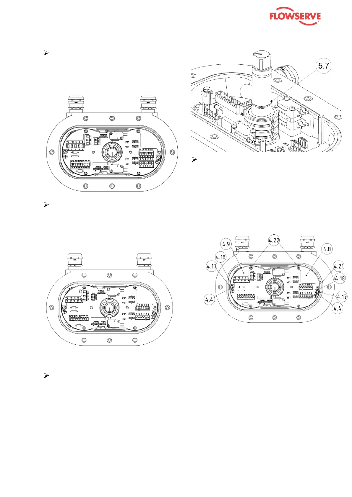
Remove the circlip (5.7).
Remove all the parts that are num-
bered in the illustration:
- screws (4.22), 2 x, and (4.21)
- shoulder screws (4.17) with terminal
clamps (4.18) on both sides
- cheese-head screws (4.4)
- cover plates (4.8) and (4.9)