EN – 13
See Figure 22.
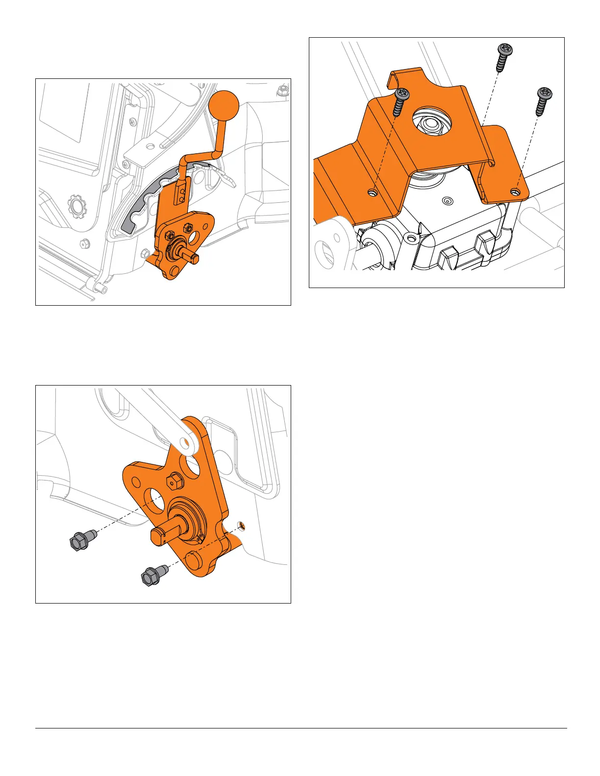
34. Place cutting height adjustment lever in the 6.4 cm
(2 1/2”) position.
See Figure 23.
35. Remove hardware retaining rear axle assembly to
deck.
IMPORTANT: Mounting hardware is present on both sides
of unit.
36. Place unit in service position. See Service Position on
page 7.
37. Remove belt from crankshaft.
38. Remove axle assembly from unit.
39. Remove hardware retaining belt guide and remove
belt guide from gearbox assembly. See Figure 24.
40. Remove drive belt and discard.

 Loading...