900 Series V5.1: Installation Guide, February 2000 9
3.1.2. Manual call point - DM960/DM990
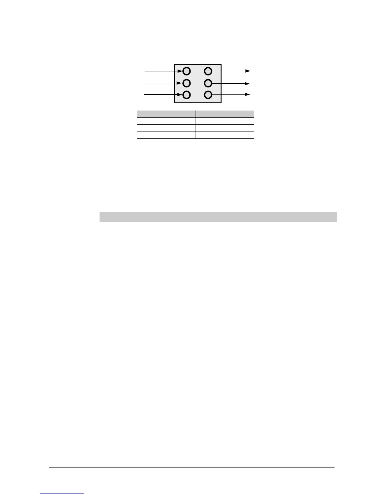
Figure 5: Wiring diagram for DM960/DM990
Terminal Function
1 - 1A 17 – 28 VDC
2 - 2A Non polarised
3 - 3A Not used
3.2. Fire monitoring controllers
The address of a fire monitoring controller is set on a seven-segment DIL switch located
on the device. Each segment of the switch must be set to “0” (ON) or “1” (OFF) using a
small screwdriver or similar tool. Please refer to Table 1: Aritech Series 9xx products for
address settings.
Table 2: DIL address settings
ADDR 1234567 ADDR 1234567 ADDR 1234567
1 1000000 43 1101010 85 1010101
2 0100000 44 0011010 86 0110101
3 1100000 45 1011010 87 1110101
4 0010000 46 0111010 88 0001101
5 1010000 47 1111010 89 1001101
6 0110000 48 0000110 90 0101101
7 1110000 49 1000110 91 1101101
8 0001000 50 0100110 92 0011101
9 1001000 51 1100110 93 1011101
10 0101000 52 0010110 94 0111101
11 1101000 53 1010110 95 1111101
12 0011000 54 0110110 96 0000011
13 1011000 55 1110110 97 1000011
14 0111000 56 0001110 98 0100011
15 1111000 57 1001110 99 1100011
16 0000100 58 0101110 100 0010011
17 1000100 59 1101110 101 1010011
18 0100100 60 0011110 102 0110011
19 1100100 61 1011110 103 1110011
20 0010100 62 0111110 104 0001011
21 1010100 63 1111110 105 1001011
22 0110100 64 0000001 106 0101011
23 1110100 65 1000001 107 1101011
24 0001100 66 0100001 108 0011011
25 1001100 67 1100001 109 1011011
26 0101100 68 0010001 110 0111011
27 1101100 69 1010001 111 1111011
28 0011100 70 0110001 112 0000111
29 1011100 71 1110001 113 1000111
30 0111100 72 0001001 114 0100111
31 1111100 73 1001001 115 1100111
32 0000010 74 0101001 116 0010111
33 1000010 75 1101001 117 1010111
34 0100010 76 0011001 118 0110111
35 1100010 77 1011001 119 1110111
1 1A
2 2A
3 3A
Loop input
terminals
Loop output
terminals