32 900 Series V5.0: Installation Guide, April 1999
• The total capacitive load on the barrier must not exceed 70 nF, even for systems
used in gas groups.
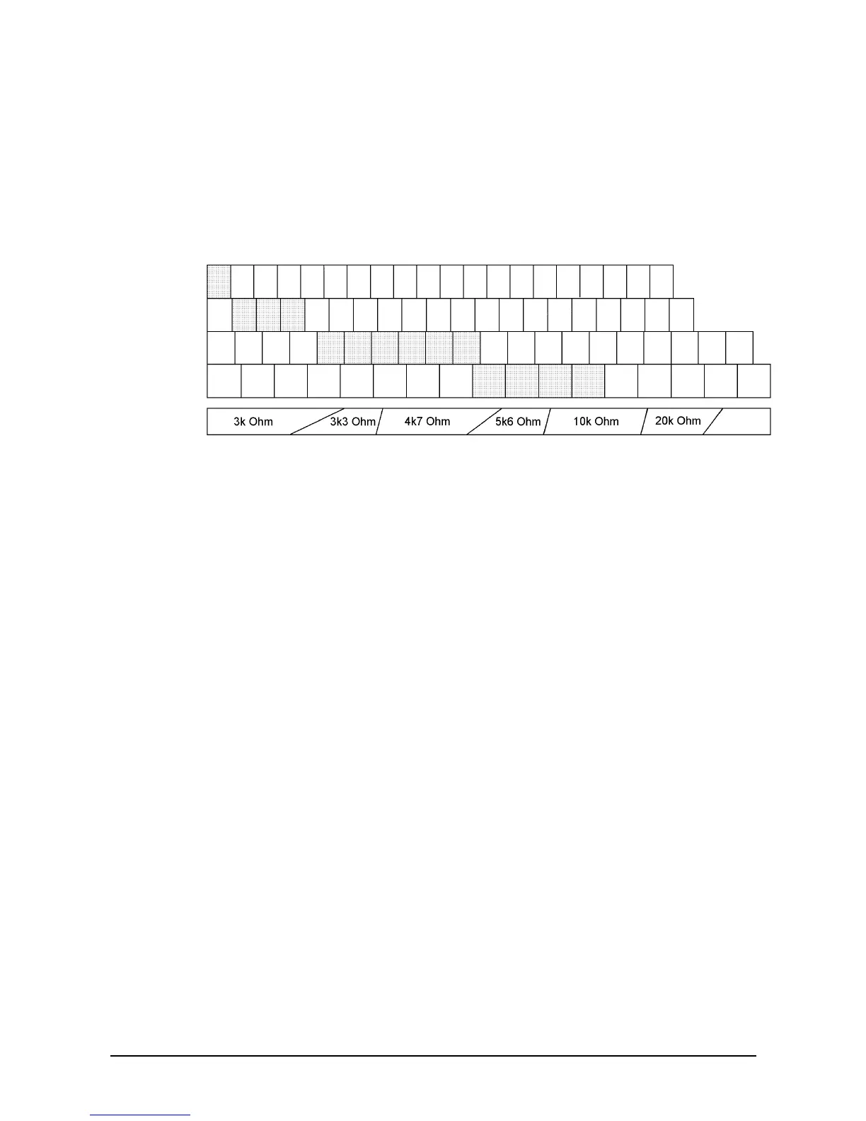
• The total circuit (current) loading when operating at the maximum capacitive loading
of 70 nF must be between 5 and 6 mA. To achieve this current on a lightly loaded
circuit, a loading resistor can be used across the line in the hazardous area circuit.
Choose a resistor value that gives a total current drain (Series 970 devices plus
resistor current) of 5-6 mA at 14 V (See Figure 27). The system certification permits
a minimum value of 3 kOhm for this shunt resistor.
Figure 27: Loading resistor diagram of an Intrinsically Safe zone
• When operating at the maximum capacitive loading of 70 nF and a current loading of
6 mA, the number of LEDs that can be illuminated simultaneously should be
restricted to one. Any attempt to illuminate more than one LED when the standing
current is 6 mA can result in communication errors.
• By adhering to these conditions it is possible to connect up to two intrinsically safe
spurs to a loop, in addition to any safe area equipment. A spur can have up to 20
devices connected. However, the maximum number of optical detectors is restricted
to 17 per spur.
• The above requirements are intended to ensure correct operation, even with long
safe-area cables and below-average loop voltages. Aritech strongly recommends
that these conditions are maintained wherever possible. If cable runs are short, or a
small number of Intrinsically Safe spurs are involved, it will be possible to work with
higher cable capacitance. Higher current loading will then be required to maintain
pulse shapes. Further guidance on these cases can be obtained from your local
Aritech Office.
4.1.3. Wiring and cable types
It is not permitted to connect more than one circuit in the hazardous area to any one
safety barrier, and that circuit cannot be connected to any other electrical circuit.
Both separate and twin cables can be used. A pair contained in a type 'A' or 'B' multi-core
cable (as defined in clause 5.3 of BS 550]: Pt 9: 1982/EN50 039) can also be used,
provided that the peak voltage of any circuit contained within the multi-core does not
exceed 60 V.
The capacitance and either the inductance or the inductance to resistance (L/R) ratio of
the hazardous area cables must not exceed the parameters specified in Table 2. The
reason for this is that energy can be stored in a cable and you must use cable where this
stored energy cannot ignite an explosive atmosphere.
To calculate the total capacitance or inductance for the length of cables in the hazardous
area, refer to Table 7: Resistance, inductance and capacitance, which gives typical per
kilometre capacitance and inductance for commonly used cables
MCP
Heat
Ion
Optical
None