900 Series V5.1: Installation Guide, February 2000 37
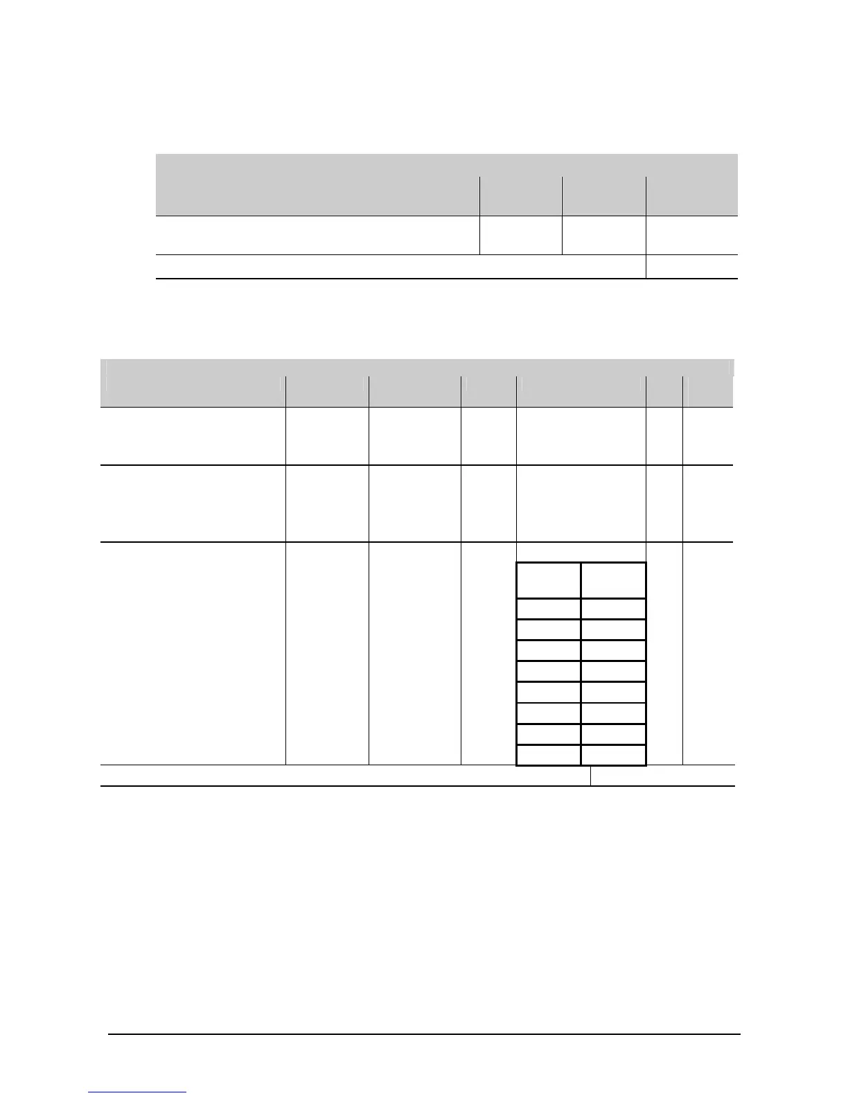
6.2.2. Alarm current
LOOP X
Table 6: Device alarm current
ALARM CURRENT
Device Quantity Alarm
Current (A)
Total (A)
Maximum number of LED's that can be switched on
per loop in alarm
0.004
TOTAL
6.2.3. Loop resistance
Table 7: Resistance, inductance and capacitance
RESISTANCE
Device Code Resistance No. Total
(Ohm)
Panel source FP1100
FP1200
FP2000
10.00 1
10.00
Isolators IU950 0.2
IU950D 0.2
DB960 0.2
DB961 0.2
Cable µF
R mH
Core to
core
Core to
sheath
No. Total
(Ohm)
2L1.0 MICC 0.017
Note: Resistance in Ohm/m/core
2L1.5 MICC 0.011 0.534 0.19 0.21
Inductance in mH/km
2L2.5 MICC 0.1168
Capacitance in µF/km
FP200 1.0 0.0181
FP200 1.5 0.0121 0.08 0.15
FP200 2.5 0.0074
(Paired by 2) WS104 0.05
(Paired by 2) WC104 0.020635
TOTAL