24 900 Series V5.0: Installation Guide, April 1999
for monitoring, manual call points must be connected between the zone monitor and
the first detector (see Figure 20).
5. The zone monitor includes a bi-directional isolator. Consequently a single short-
circuit on the loop wiring adjacent to the zone monitor does not affect the operation
of the conventional detector zone.
Two LEDs are visible through the top cover of the enclosure. The red LED illuminates
when an alarm condition is detected. The yellow LED illuminates when the built-in isolator
senses a short-circuit loop fault.
3.4.2.2. Sounder control unit – IO956D
Function:
The Series 950 DIN-rail sounder control unit is used to control the operation of a
zone of externally powered sounders and to report their status to the analogue
control equipment.
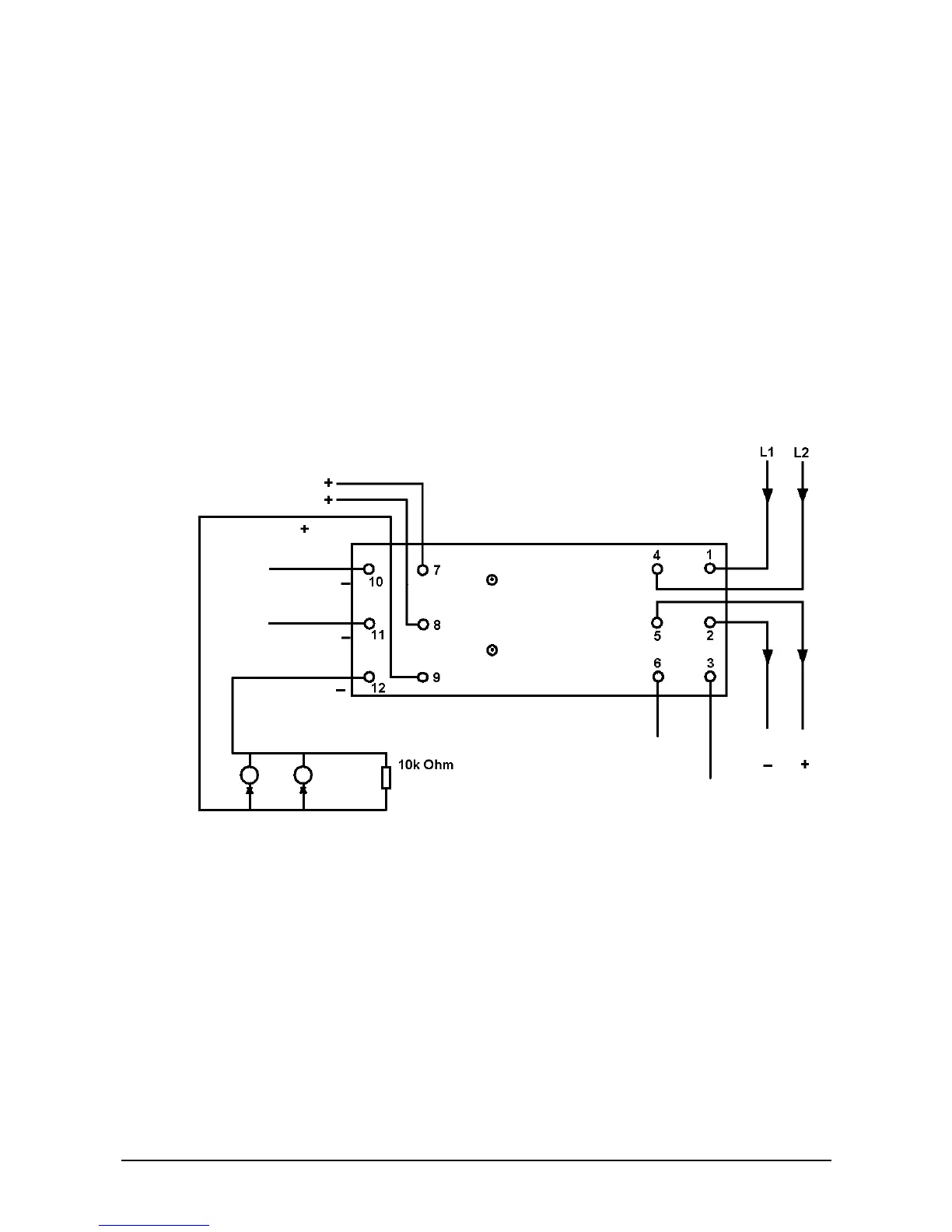
Figure 21: Wiring connections (Sounder control unit – DIN mount)
Features:
The sounder control unit allows sounders to be operated continuously or be
pulsed, 1 second on, 1 second off. Sounders can be operated individually or in
groups and, whichever address mode has been applied, can be synchronised
when in pulsed operation.
An opto-coupled input is provided to monitor the state of the external power supply.
Sounders ON
Fault
Fault input common
Fault input N/C
Sounde