900 Series V5.1: Installation Guide, February 2000 19
5. Use a small screwdriver or similar tool to set the unit address on the address switch.
Segments, numbered 1 to 7, must be set to 0 or 1 in accordance with the address
table.
6. Fit the adhesive label provided over the aperture through which the DIL switch is
accessed. This label must be fitted to ensure proper protection of the internal circuitry.
Failure to fit the label invalidates the IP rating.
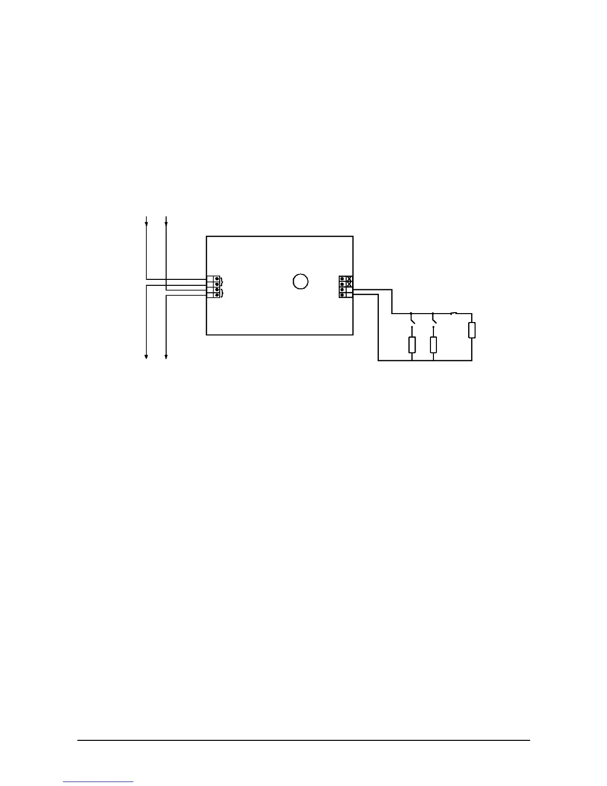
3.3.6. Switch monitor - II952
There are eight terminals, four for the loop connections (incoming and outgoing), two for
the external switch connection, and two unused connections.
Figure 14: Wiring diagram for the Switch Monitor Unit
To install the switch monitor:
1. Mount the Switch Monitor Unit. The Series 950 switch monitor is not designed for
outdoor use unless it is mounted in a suitable weatherproof enclosure.
2. Connect the communication line to the L1 and L2 inputs. The inputs are unpolarised,
but it is recommended to keep L1 negative for consistency.
3. Connect the switch contacts to the switch inputs. The switch input is monitored for
open or short circuits.
À
SW –