900 Series V5.1: Installation Guide, February 2000 15
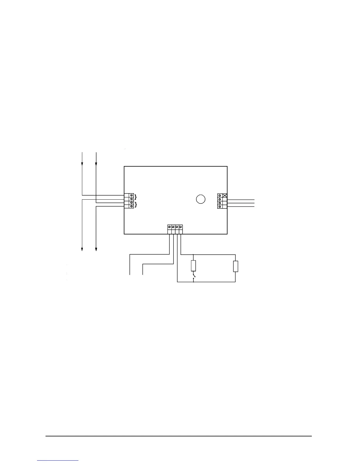
3.3.2. Single channel input/output unit - IO950
Twelve terminals are provided:
• Four for the loop connections (incoming and outgoing)
• Two for an opto-isolated external input
• Two for an end-of-line supervised input
• One for the relay pole
• One for the normally open contact
• One for the normally closed contact
• One unused terminal
Figure 10: Single channel input/output unit
3.3.3. Three channel input/output unit - IU922
There are 26 terminals:
• Four for the loop connections (incoming and outgoing)
• Four for the power supply in and out
• Three sets of six terminals, each providing
• One relay pole,
• One normally open contact
• One normally closed contact
• One logic input
• One supply out
Series 950 loop
Relay output
1 A @
30 V Max.
30 V AC or DC
20 kOhm
EOL
4.7 kOhm
N/O input
contact
L1 (-ve)*
L2 (+ve)*
Optional monitoring of an
external voltage
<1 V = logic 0 >4 V = logic 1
Do not exceed 35 V
Not polarity sensitive
* L1 and L2 are polarity insensitive but it is recommended to
keep L1 negative for consistency.
N/C
COM
N/O
OPTO
OPTO
I/P +
I/P -