12 900 Series V5.0: Installation Guide, April 1999
3.2.2. Zone monitoring unit - II955
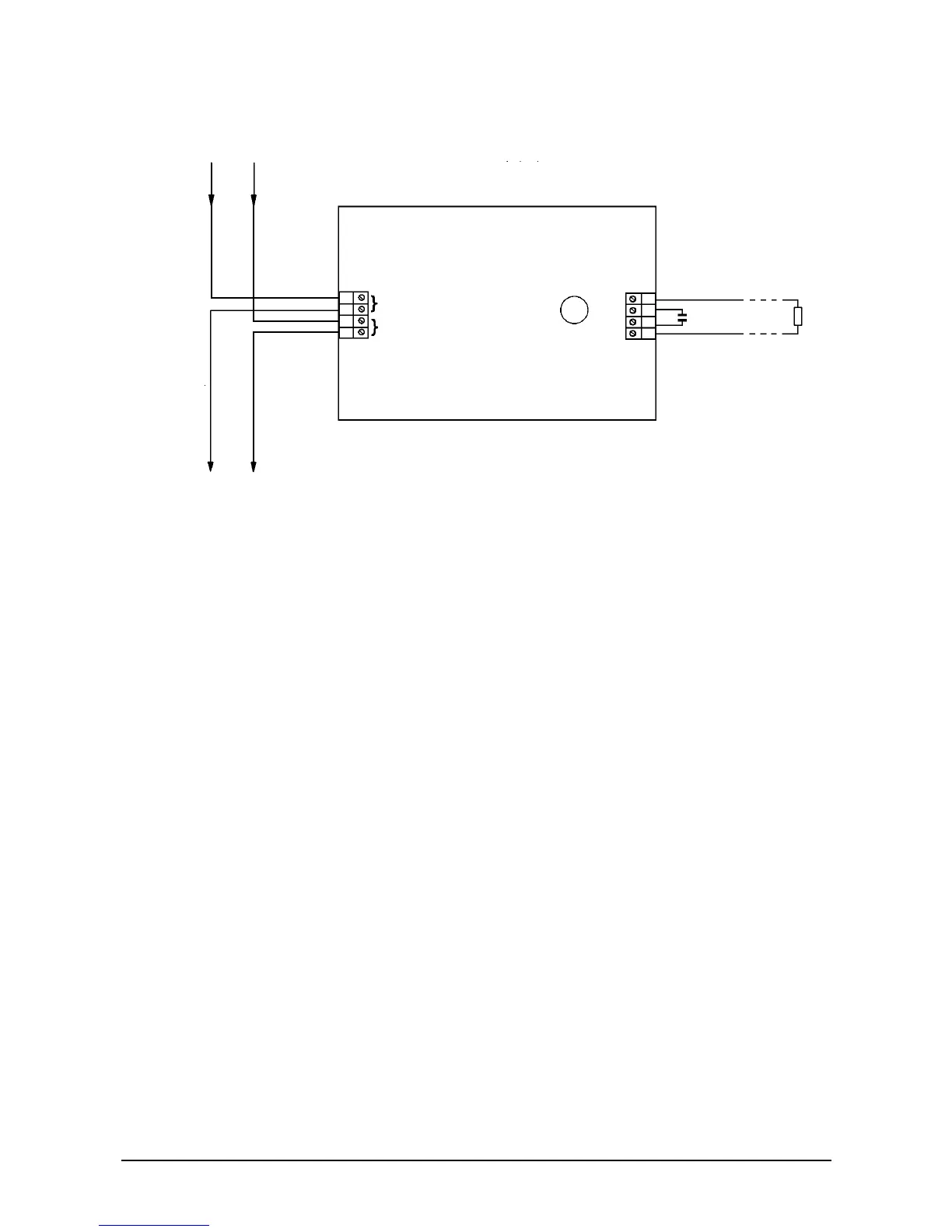
Figure 7: Wiring diagram for zone monitoring unit
A 6.2 kOhm resistor must be placed at the end of the line.
A Manual Call Point acts as a Manual Call Point warning.
-
Where (non-addressable) intrinsically safe detectors are used, you must
place a 28 V/300 Ohm safety barrier inside the safe area adjacent to the
hazardous area. When used in this configuration, the wire link adjacent to
the LED must be cut to provide correct short-circuit monitoring (see chapter
4: Intrinsically Safe Products - 970 Series
Maximum number of conventional fire detectors: 20
Shielded cable is preferred but not compulsory.
The Series 950 Zone Monitor can be used with active end-of-line units that
operate with diode bases with a capacitor to the zone output. The capacitor
must not exceed 50 µF (nominal) and must be connected as shown.
3.2.3. Loop powered sounder - AS950
The Series 950 loop sounder has an output of 85 dB(A) at 1 meter. It is used with Series
950 analogue, addressable fire monitors. You can use 20 sounders on a Series 950 loop
in 85 dB mode.
Series 950 loop sounders are designed to comply with BS5839, Part 1: 1988 and are
particularly suitable for rooms, corridors and other confined spaces. They are supplied as
a sounder base or a sounder base with a cap for use as a stand-alone sounder.
The control panel activates the sounders. The sounder can be switched on in pulsed
mode, 0.5 s on, 0.5 s off, or switched to operate in continuous mode with an alternating
tone, 0.25 s 500 Hz, 0.25s 550 Hz.
SERIES
950
LOOP
* L1 and L2 are polarity insensitive but it is recommended to keep L1
negative for consistency.
Capacitor used
only if active
EOL is fitted
ZONE +
6.2 kOhm
active EOL
ZONE -
L2 (+ve) *
L1 (-ve) *