900 Series V5.1: Installation Guide, February 2000 11
regular intervals and compensates for the positive drift of
the signal.
Remote interface: The optical and electronic elements of the detector are
separate from one another, with most of the electronics
housed in the interface. Consequently the interface can
be installed in an accessible position. You can easily
service the electronics of the beam detector without using
access equipment.
Simple wiring: The transmitter and the interface of the detector can be
wired to the nearest point of the loop. No extra wiring is
necessary.
Simple alignment: During commissioning it is necessary to align the
transmitter and receiver so that the beam is correctly
projected at the receiver. As the beam is invisible, the
alignment procedure has been traditionally complicated.
However, the detector makes alignment simple – a high-
brightness LED behind the receiver lens flashes while the
transmitter is being aligned. Once the alignment is
correct, the LED stops flashing.
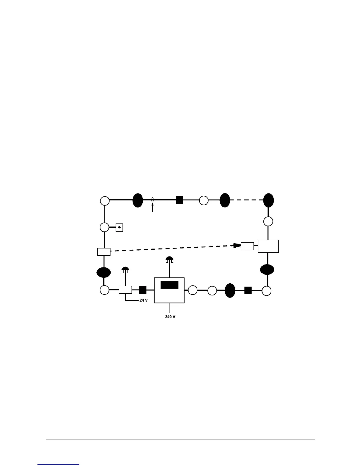
Figure 6: Wiring diagram for Series 950 beam detector
À Beam detection interfaces à 2-core
Á Control panel Ä Remote LED
 Up to 20 devices
¦
§
¨
©
TX
RX
SCU
ª
INTERFACE:
• Loop-powered
• Polarity insensitive
TRANSMITTER:
• Loop-powered
• Does not use address
• Can also be powered
from 24 VDC supply
• Polarity insensitive