26 900 Series V5.0: Installation Guide, April 1999
3.4.3. Input/output units
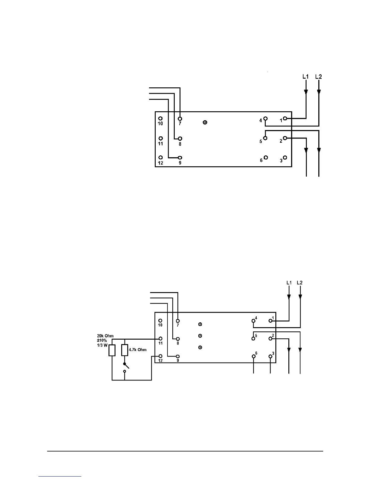
3.4.3.1. Output unit - IO955D
Figure 22: Wiring connections (output unit – DIN mount)
The Series 950 DIN-rail output unit provides a voltage-free, single pole, changeover relay
output. The unit is loop powered.
One red LED is visible through the top cover of the enclosure. This LED illuminates when
the relay is set. It can be disabled to reduce loop current by using the DIL switch.
3.4.3.2. Input/output unit - IO950D
Figure 23: Wiring connections (I/O unit – DIN mount)
N/O
COM
NC
Series 950 loop
-
: Line 1 and Line 2 are polarity insensitive but it is recommended to
keep L1 negative for consistency.
Relay ON
Relay output
1 A AT 30 V
Max. 30 VAC or
DC
Relay ON
Switch closed
Fault
Series 950 loop
Optional monitoring of an
external voltage
<1 V = LOGIC 0
>1 V = LOGIC 1
Do not exceed 35 V
Not polarity sensitive
−
Line 1 and Line 2 are not polarity sensitive but it is recommended to
keep L1 negative for consistency.
N/O input
contact
Relay output
1 A AT 30 V
Max. 30 VAC or
DC
COM
N/O
NC