14 900 Series V5.0: Installation Guide, April 1999
-
The cables connected to the sounder output must be able to power
sounders, e.g. MICC.
3.3. Input/output units
Set the address of an input/output unit using the lower seven-segments of the DIL switch.
Each segment of the switch must be set to “0” (ON) or “1” (OFF), using a small
screwdriver or similar tool. Please refer to section 3.2.
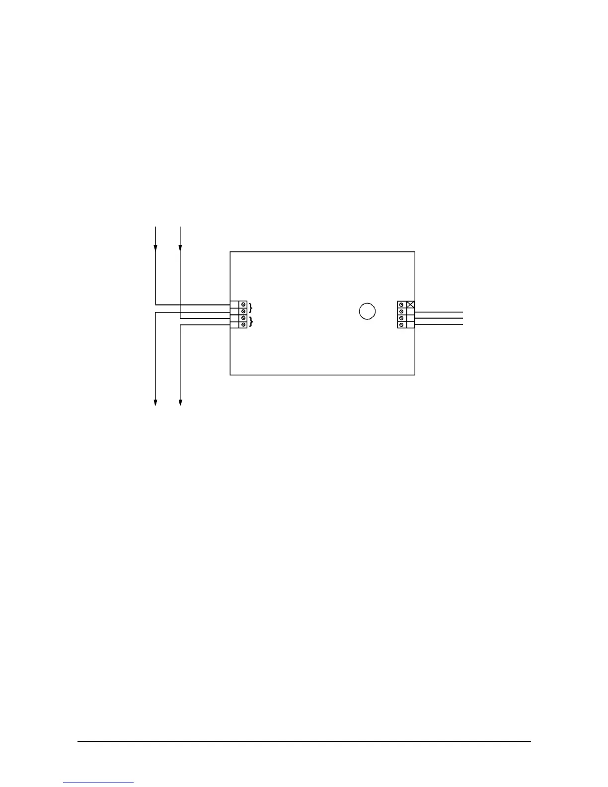
3.3.1. Single channel output unit - IO955
Figure 9: Single channel output unit
Eight terminals are provided:
• Four for the loop connections (incoming and outgoing) with two for the positive
supply
• One for the relay pole
• One for the normally open contact
• One for the normally closed contact
• One unused terminal
Relay output
1 A @ 30 V
max. 30 V