16 900 Series V5.0: Installation Guide, April 1999
• One unused terminal
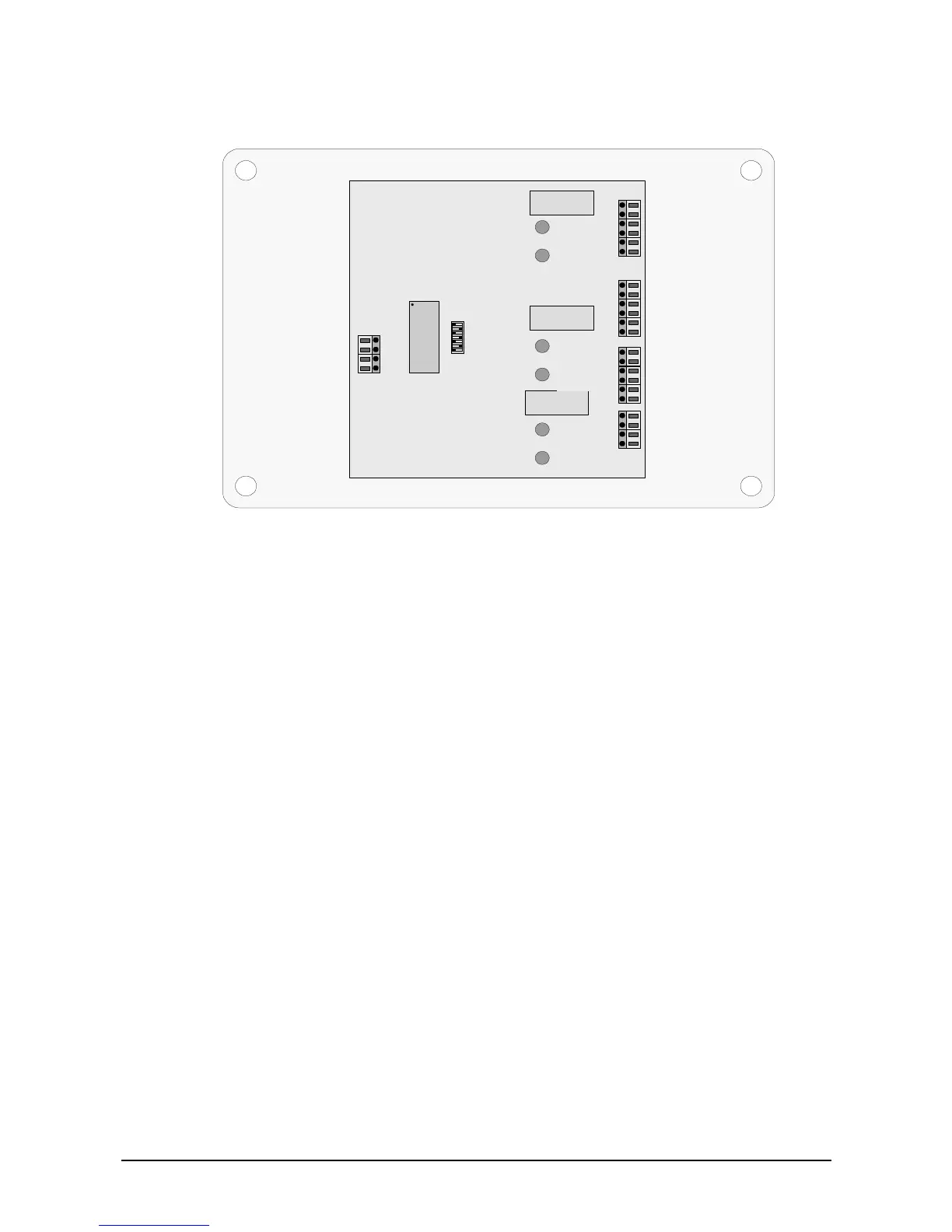
Figure 11: Three-channel input/output unit
+ve supply out
Local input 1
N/C relay 1
Pole relay 1
N/O relay 1
OV out
+ve supply out
Local input 2
N/C relay 2
Pole relay 2
N/O relay 2
OV out
+ve supply out
Local input 3
N/C relay 3
Pole relay 3
N/O relay 3
OV out
+ve supply in
+ve supply out
-ve supply in
-ve supply out
-ve line out
-ve line in
+ve line out
+ve line in
LED 1
(O/P)
LED 2
Addressing
switch
Custom
chip
Relay 3
Relay 1
Relay 2
TB1
-
24 VDC is required to activate the inputs.
Connect ‘+Ve supply out’ to local input 1,2 or 3.
A 24 VDC power supply is required to operate the I/O unit.
Maximum input resistance: 100 kOhm
Maximum input capacitance: 200 nF
3.3.4. Mini Switch Monitoring Unit - II950
There are six wires for the loop connections, two for driving a remote indication and two
for an external switch connection.