900 Series V5.1: Installation Guide, February 2000 23
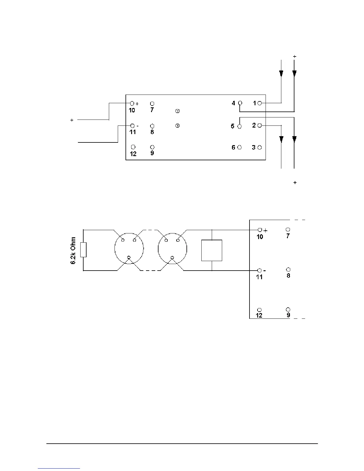
Figure 19: Zone connection – Standard bases with 6.2 kOhm monitoring resistor at
end-of-line
Figure 20: Zone connection – Diode bases with active EOL device
- Notes on usage:
1. Zone voltage is regulated to 19 + 1 V for any loop voltage greater than 22 V. If the
loop voltage falls below 22 V, the zone voltage is approximately 1.5 V below the loop
voltage. It is important to ensure that under worst-case conditions, the zone voltage
is above the minimum operating voltage for the conventional detectors.
2. Alarm conditions are latched internally by the zone monitor. You therefore must
reset the alarm even if non-latching conventional detectors are used.
3. The zone monitor can be used to power and control intrinsically safe detectors via
safety barriers with resistance values between 300 Ohm and 350 Ohm. To use the
Zone Monitor with intrinsically safe devices, cut the wire link near the DIL switch
(Refer to chapter 4: Intrinsically Safe Products - 970 Series).
4. Manual call points can be located at any point in the zone wiring if active end-of-line
monitoring with diode detector bases are used. If a 6.2k Ohm 1/3 W resistor is used
DIN-rail zone monitor
Note: The zone monitor is polarity sensitive
Zone
output
Alarm
Fault
Series 950 loop
EOL MCP