Do you have a question about the Armstrong The Brain DRV80 and is the answer not in the manual?
Explains the meaning of safety warning symbols used in the manual.
Covers general advisories, data policy, patents, and compliance with standards.
Lists all items included in the DRV80 product package.
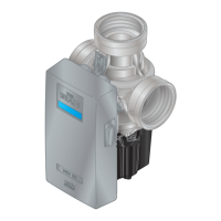
Provides detailed measurements and diagrams of the DRV80 unit.
Covers protection, materials, pressures, and temperature limits.
Details recirculation, flow rates, electrical supply, and auxiliary relay.
Describes how default settings are derived from the Installation Detail Form (IDF).
Provides general guidance and safety precautions for installing the DRV80.
Lists essential requirements for proper DRV80 installation.
Illustrates system configurations and component legends.
Detailed steps for physically installing the DRV80 unit.
Details the process to bring the DRV80 and system online.
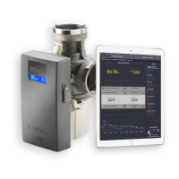
Guide to connecting and using the DRV80 control software.
Overview of software features and steps to select the correct COM port.
Explains how to view unit serial number, software version, and manufacturing date.
How to input and set the desired outlet water temperature via software.
Modifying Min, Max, and Default setpoint values for the application.
Choosing temperature units and setting up alerts and relay activation.
Detailed explanation of setpoint ranges and default value behavior.
How alerts are triggered and their effect on the relay contacts.
Describes the default Level 1 and Level 2 alerts for the DRV80.
Explains the manual thermal disinfection procedure and critical safety warnings.
Configuring disinfection parameters like timeout and setpoint within the software.
Guide to determine and set disinfection cycle times and parameters.
Steps for executing standard thermal disinfection cycles.
Setting the DRV80 address and network protocol for communication.
Explains specific alert messages like 'Temp High' and 'Temp Low'.
Explains specific error messages like 'Error PCB' and 'Error Drive'.
Details connectivity via SAGE® BS and Modbus protocols.
Discusses flow rate and temperature differential for optimal operation.
Recommended inspections and replacements for seals, strainers, etc.
Guidelines for battery inspection, replacement, and usage.
Essential safety steps before disassembling the DRV80.
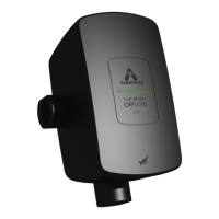
Lists parts and part numbers for the electronics module.
Diagram showing connections for power, motor, battery, and communication ports.
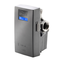
Identifies individual parts and part numbers for the main DRV unit.
Steps to calibrate the valve after replacing key components.
Solutions for specific error messages displayed on the unit.
Troubleshooting common operational problems and their causes.
Details the warranty period, limitations, and exclusive remedy.
| Brand | Armstrong |
|---|---|
| Model | The Brain DRV80 |
| Category | Control Unit |
| Language | English |