12
Armstrong International
Parc Industriel Des Hants-Sarts, 2ème Avenue No. 4, Haerstal, B-4040, Belgium
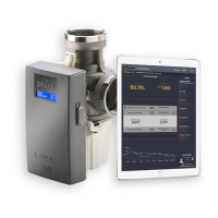
armstronginternational.com/brain
H C
Isolation Valve
Sink
Shower
Thermometer
Strainer
Cold Water
Hot Water
Mixed Water
Check Valve
Recirculation Pump
System Layout
- Legend -
Stop Valve
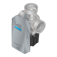
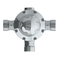
DRV80 Assembly
Swing Check Valve*
- Legend -
Thermometer
Isolation Valve
*Orientated for piping
schematic detail only.
Must be installed in
horizontal plane.
Outlets
Return to
Hot Water
Supply Inlet
Cold Water
Supply
Mixed Return
From Hot Water
Supply
Outlets
DRV
Mixed Flow
Piping Diagrams
Items are installer
supplied
Figure 12-1. Single Valve Installation
Note: For 0-90 GPM (0-340 l/min) Systems the DRV80 inlet connections are 2”
Note: For 0-150 GPM (0-567 l/min) Systems the DRV80 inlet connections are 3”
 Loading...