DIS-IP2 DESKTOP CALL STATION
USER MANUAL
page 12/37 armtel.com
© Armtel info@armtel.com
The main board includes the following:
− Х8, Х9 – connectors for connection of Ethernet with РоЕ function;
Indicators on the connectors:
1) Green – lights, when physical connection with Ethernet is established, flashes, when
the network interface is active (packet data receipt or transfer);
2) Orange – lights with the device supply from PoE source;
− Х17 – connector for ADSL connection;
− Х13 – not used;
− Х5 – connector for Wi-Fi antenna connection;
− Х26 – connector for connection of external expansion unit DIS
ARMT.665230.207;
− ХР4…ХР7 – connectors for pushbutton connection;
− Х15, Х16 – connectors for built-in loudspeakers connection;
− Х14 – microphone connector;
− Х19 – connector for external 12 V power supply connection;
− Х18 – connector for external 48 V power supply connection;
− U13 – ADSL module (to be installed in versions -04…-07 –Table 1);
− S4 – return to default settings button.
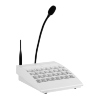
1.2.3 LED pushbuttons
The LED pushbuttons are located by eight pieces in the row (pushbutton module).
Depending on the version, it can be from 8 to 32 pushbuttons (Table 1). The communica-
tion function can be assigned to any pushbutton.
Each pushbutton has backlight with two LEDs placed under it. The LED indication
mode for each pushbutton, the direct call pushbuttons included, are assigned by the soft-
ware.
The main variants of pushbutton indication:
− when pressing the pushbutton, the backlight is activated for the period of
pushbutton hold;
− the first pressing the pushbutton activates the backlight, the repeated one
deactivates it;