DIS-IP2 DESKTOP CALL STATION
USER MANUAL
page 18/37 armtel.com
© Armtel info@armtel.com
In the process of call, transfer or receipt of messages the indicators on the corre-
sponding pushbuttons, depending on the functions setting can signal about the communi-
cation organization results by flashing with different degree of intensity.
The types of pushbutton signaling DIS-IP2 within the SIP and «Armtel-IP» protocols
are given in Appendix D.
Also, using the software "Configuration Tool of IPN2 system" RMLT.00041-01 34 01,
the file with the default settings can be changed. To do this, select the edited device and
click the "Save file config" button. This will copy the current device configuration to the de-
fault settings file on the device. The "default.par" file is available for downloading and up-
loading via the TFTP protocol.
2.4.3 To return to the default settings, remove the cover (2, Figure 2) from the case (1,
Figure 2), press and hold the "S4" button (Figure 4) on the DIS-IP2 board for at least 5 sec-
onds. After releasing the button, the configuration file is read with the default settings "de-
fault.par", followed by saving the settings to the main configuration file and rebooting the
device. After the end of the reboot process, the device starts working with the default set-
tings. Then replace the cover.
N o t e s
1 Return to default settings after power on and boot DIS-IP2.
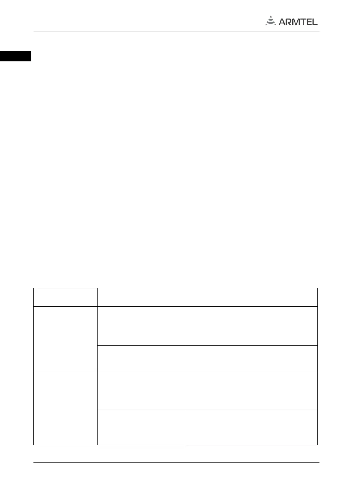
2.4.4 Troubleshooting list
If there is a malfunction, poor audibility, etc. – call the person responsible for the op-
eration of DIS-IP2. The troubleshooting are given in Table 4.
Table 4 – List of possible malfunctions and actions for their elimination
Problem Possible Cause Action
Subscriber cannot
make and receive
calls
No supply on the device
Check the reliability of supply connec-
tion, be assured that supply voltage is
delivered to the subscriber device
DIS-IP
Upload the correct configuration param-
eters
the network con-
nector (pos. 6 Fig-
ure 2) is off
Lack of supply by PoE line
Check the connection reliability, be as-
sured that supply is delivered through
PoE line
Overload on PoE
line
May be accompanied by short time or-
ange flashings on the connector.
the value of load current on РоЕ line