TD 92022EN
3 July 2013 / Ver. G
Installation Guide
H/U952T Terminal Transmitter
9
3.5 Connection of Buses and Control Equipment
Buses are connected either via modular bus cabling or twisted-pairs.
NOTE: Data buses are polarized! Use only twisted-pairs for
separate wiring!
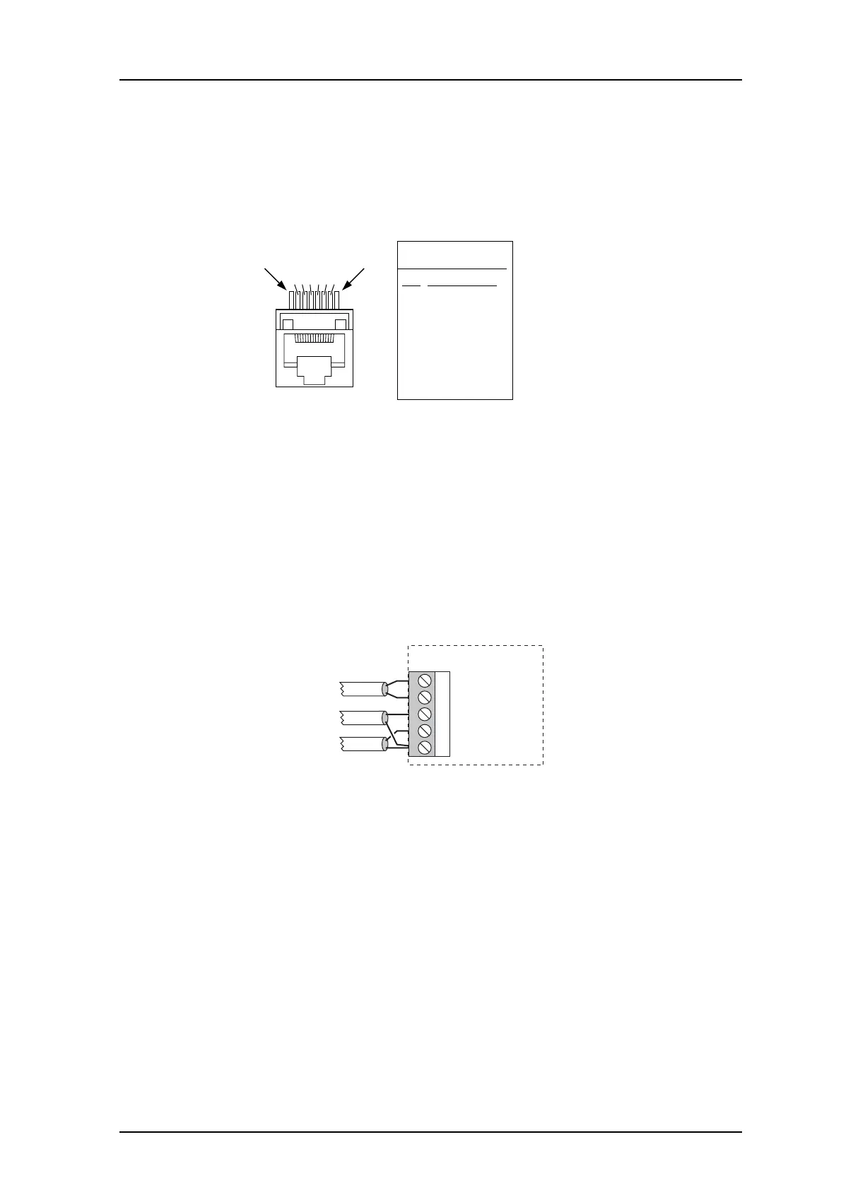
Bus Connections via Modular Bus Cabling
Pin 1
234567
Pin 8
Pin
1
2
3
4
5
6
7
8
Signal
A1 data bus
A2 data bus
B1 data bus
B1 data bus
D1 data bus
D2 data bus
SP1 speech bus
SP2 speech bus
J100 + J101
Figure 5. Modular bus cable pins.
Note that only D- and SP-bus are used by the Terminal Transmitter. When the modular b
us
cable is used, no further connection of the SP-bus to T952SM/FL Speech and Frequency Lock
Module is required.
• Connect the modular bus cabling to connectors J100 and J
101, see figure 2 on page 3.
Bus Connections via Twisted-Pairs
J103
1 D1
2 D2
3 Booster control
4 Monitor input
5 GND
H/U952T
D-bus, connection
to a Central Unit
Control of
Power Amplifier
H/U950SC
• Connect the D bus to connector J103, screw 1 and 2.
• If speech is used, see Connection of SP/FL Bus via Twisted-Pairs on page 17.
Connectio
n of Control Equipment
• Connect H/U950SC Output Power Surveillance Module to J103, screw 4 and 5.
See also the Installation Guid
e for the respective unit
s.