TD 92022EN
3 July 2013 / Ver. G
Installation Guide
H/U952T Terminal Transmitter
16
Appendix A: Installation of T952SM/FL Speech and Frequency Lock Module
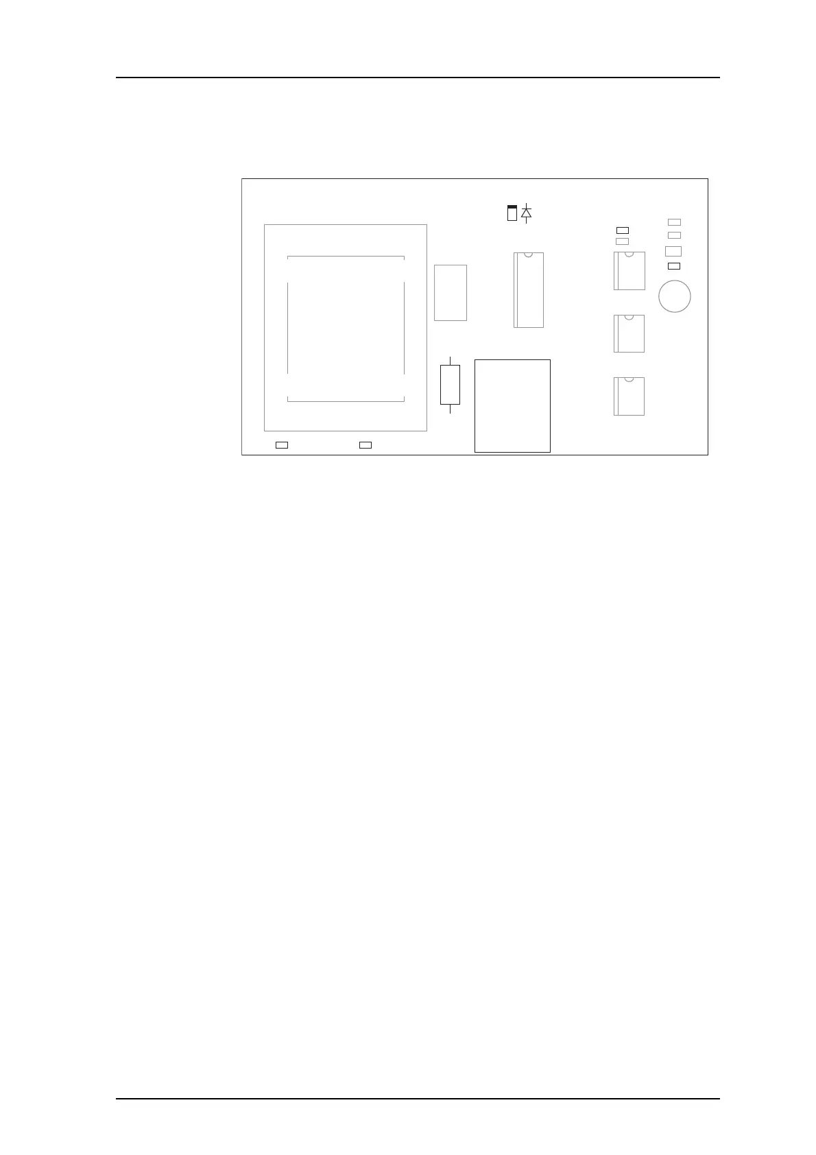
Board Description
2500 3125
R100
J100
R202
R211 R212
1
R203
952SM/FL
LED100
2
1
1
1
+
-
Figure 6. Circuit Board for 952SM/FL.
Connections, etc.
J100
Screw terminal, for speech bus (SP-bus) if system bus cabling is not
used.
LED100 Indicates frequency locking (red).
R100 Speech bus termination resistor.
R211, R212 The mounted resistor indicates the reference
frequency used
(default 3125 Hz).
R202, R203 These resistors have to be exchanged when reference
frequency 2500 Hz is used.
Changing Re
ference Frequency to 2500 Hz
1 Move R212 to R211
2 Change R202 from 33 k to 39 k (tolerance 1%).
3 Change R203 from 34.8 k to 47 k (tolerance 1%).
Installation
• Plug the T952SM/FL Speech and Frequency Lock modu
le onto the connector J200 on the
Terminal Transmitter board, s
ee figure 2 on page 3.